A pressure frame for thin plate splicing submerged arc welding machine
What is Al technical title?
Al technical title is built by PatSnap Al team. It summarizes the technical point description of the patent document.
A submerged arc welding machine, pressure technology, applied in arc welding equipment, welding/welding/cutting items, welding equipment and other directions, can solve the problems of small operation space, fixed gantry, large and complex equipment, etc. The effect of high site utilization, wide applicability and simple mechanical structure
Active Publication Date: 2021-06-25
SHANGHAI SHIPBUILDING TECH RES INST
View PDF7 Cites 0 Cited by
Summary
Abstract
Description
Claims
Application Information
AI Technical Summary
This helps you quickly interpret patents by identifying the three key elements:
Problems solved by technology
Method used
Benefits of technology
Problems solved by technology
[0005] The purpose of the present invention is to provide an improved pressure frame for thin plate splicing submerged arc welding machine, which can not only overcome the inconvenient and unreliable pressing in the prior art and affect the welding quality, but also prevent the gantry from being fixed , the operating space of the station is small, and the equipment is large and complex.
Method used
Image
Click on the blue label to locate the original text in one second.
Reading with bidirectional positioning of images and text.
Examples
Embodiment Construction
[0025] The technical solutions of the present invention will be clearly and completely described below in conjunction with the accompanying drawings. Apparently, the described embodiments are part of the embodiments of the present invention, but not all of them. Based on the embodiments of the present invention, all other embodiments obtained by persons of ordinary skill in the art without making creative efforts belong to the protection scope of the present invention.
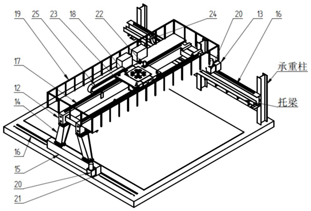
[0026] The present invention provides a pressure frame for thin plate splicing submerged arc welding machine, see for details figure 2 , 3 , The pressure frame described in 4, the pressure frame is arranged in the workshop, and its difference with the prior art is: the described pressure frame includes a semi-gantry device, a lifting and rotating device and a bilateral pressure frame device; the semi-gantry device includes a double Beams, under the two ends of the double beams, there are upper and lower fram...
PUM
Abstract
The invention relates to a pressure frame for submerged arc welding machine for thin plate splicing, which includes a half-gantry device, a lifting and rotating device and a double-sided pressure frame device; Guide rail, longitudinal motor reducer, longitudinal wheel set, trolley, transverse guide rail, transverse motor reducer, transverse wheel set, etc., can realize the longitudinal and transverse travel of the pressure frame; the lifting and rotating device consists of a hydraulic station, an oil cylinder, a lifting It is composed of pin shaft, oil cylinder frame, lifting column, guide wheel, slewing bearing, pinion, cycloid reducer, motor, etc., which can realize the lifting and rotating motion of the pressure frame. The longitudinal and lateral movement of the semi-gantry device, the lifting and rotating movement of the lifting and rotating device, and the placement of workpieces in any position and direction are all within the scope of the invention. The two-sided pressure frame is effective and reliable for the two steel plates that need to be spliced. Pressing and cooperating with related welding devices not only ensure the convenience of welding operation and high efficiency, but also ensure the quality of welding.
Description
technical field [0001] The invention relates to the technical field of thin plate splicing, in particular to a pressure frame used for thin plate splicing submerged arc welding machines. Background technique [0002] In industrial production, due to the high welding heat, the submerged arc tailor welding of thin steel plates will cause large deformation of the steel plates, resulting in poor welding quality, and even the welding work cannot be completed. Therefore, the measures of pressing the thin steel plates before welding are usually adopted. There are two pressing methods, one is to use simple guide rails and the welding machine's own weight plus auxiliary pressing iron, and the other is to use double-sided multi-head pressing with a fixed mast. [0003] The method of simple guide rail and welding machine’s self-weight plus auxiliary pressure iron is to place two steel plates spliced by spot welding on a steel platform with better flatness. A simple guide rail is lai...
Claims
Application Information
Patent Timeline
Application Date:The date an application was filed.
Publication Date:The date a patent or application was officially published.
First Publication Date:The earliest publication date of a patent with the same application number.
Issue Date:Publication date of the patent grant document.
PCT Entry Date:The Entry date of PCT National Phase.
Estimated Expiry Date:The statutory expiry date of a patent right according to the Patent Law, and it is the longest term of protection that the patent right can achieve without the termination of the patent right due to other reasons(Term extension factor has been taken into account ).
Invalid Date:Actual expiry date is based on effective date or publication date of legal transaction data of invalid patent.