A double-chamber cupping device

A technology of double air chambers and tanks, applied in the field of medical devices, can solve the problems of increasing patient pain, poor effect, skin damage, etc., and achieve the effect of avoiding pain

Active Publication Date: 2021-04-23
青岛市中医医院
View PDF4 Cites 0 Cited by
  • Summary
  • Abstract
  • Description
  • Claims
  • Application Information

AI Technical Summary

Problems solved by technology

[0004] However, due to the different operators, it is not easy to grasp the negative pressure value in the tank for this kind of structure. Excessive negative pressure may cause damage to the skin, increase the pain of the patient, and even produce tension blisters, while the negative pressure value is too small to treat And the effect is not good
Moreover, for different patients and different conditions, different negative pressure values ​​should be used to achieve good therapeutic effects. The negative pressure value in the existing cupping tank cannot be standardized and controlled, so the best therapeutic effect cannot be achieved.
In addition, the air valve of the existing manual vacuum cupping is at the top, which is often encountered when covering clothes, which can easily lead to gas leakage

Method used


Image

  • A double-chamber cupping device
  • A double-chamber cupping device
  • A double-chamber cupping device

Examples


Embodiment 1

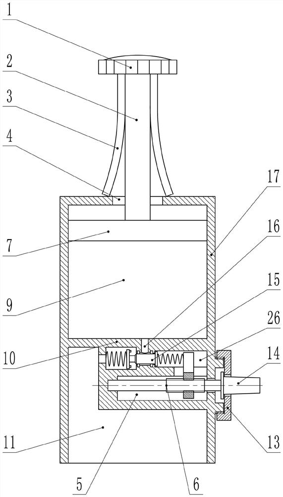
[0017] In embodiment 1, such as figure 1 , 2 As shown, the present invention includes a cylindrical tank body 17 with an open lower end, and the tank body 17 is provided with a partition 10 and a piston 7 . The partition 10 is fixed in the middle of the tank body 17 , and divides the inside of the tank body 17 into upper and lower cavities, namely an upper cavity 9 and a lower cavity 11 . The piston 7 is located in the upper cavity 9, the periphery of the piston 7 is airtightly connected to the inner surface of the tank body 17, the upper surface of the piston 7 is fixedly connected to the piston rod 2, and the upper wall of the tank body 17 is provided with a piston port 4, The piston rod 2 protrudes from the piston port 4, and the upper end of the piston rod 2 is fixedly connected to the piston handle 1. Pushing the piston 7 up and down by the piston handle 1 can change the air pressure in the cavity of the tank body 17 .

[0018] Such as figure 1 As shown, one or more s...

Embodiment 2

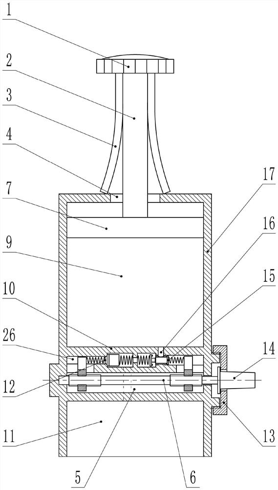
[0028] In embodiment 2, such as image 3 , 4 As shown, in addition to the technical features in Embodiment 1, this embodiment also includes an intake valve 12 . In this embodiment, except for the technical features related to the intake valve 12, other technical features are the same as those in Embodiment 1, and will not be repeated in this embodiment.

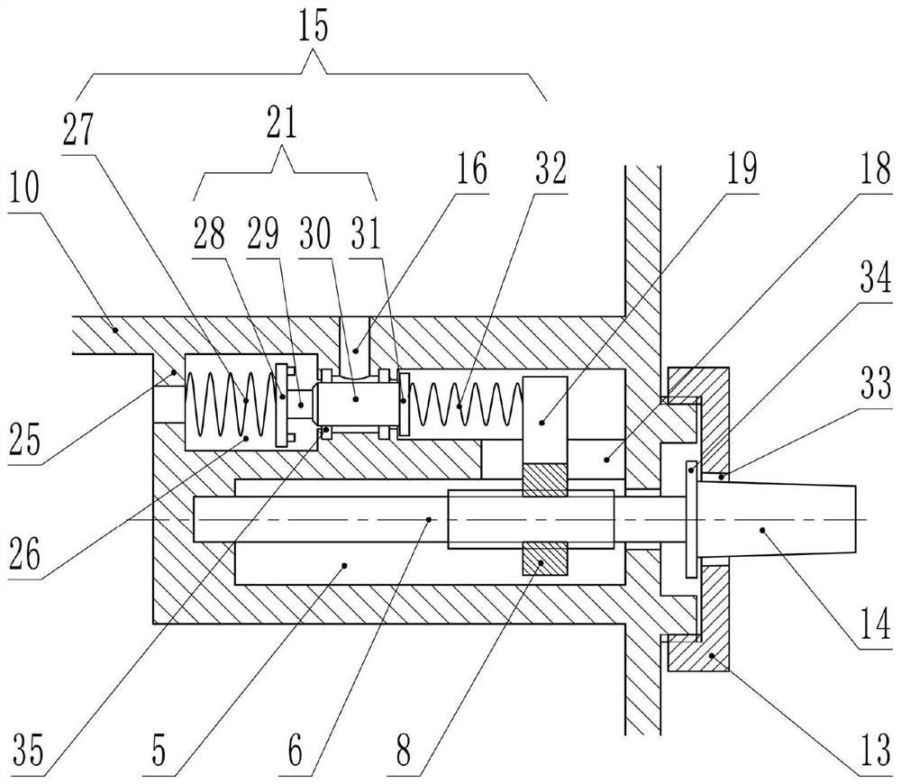
[0029] The intake valve 12 is located in the No. 2 hole 26. In this embodiment, the inner flange 25 is located in the middle of the No. 2 hole 26, and the structure in front of the inner flange 25 is the outlet valve 15. Its structure Same as Embodiment 1, the structure behind the inner flange 25 is the intake valve 12 . The intake valve 12 communicates with the outside of the lower chamber 11 and the tank body 17, and its function is to allow external air to enter the lower chamber 11 to increase the air pressure in the lower chamber 11.

[0030] Two strip-shaped holes 18 are respectively arranged between the front and re...


PUM


Abstract

The invention discloses a double-chamber cupping device, which belongs to the field of medical equipment, and is characterized in that it comprises a cylindrical tank body with an open lower end, and a partition and a piston are arranged in the tank body; the partition board is fixed on the bottom of the tank body. In the middle position, the inner part of the tank is divided into upper and lower chambers, namely the upper chamber and the lower chamber; the piston is located in the upper chamber, and the periphery of the piston is airtightly connected with the inner surface of the tank; the periphery of the piston rod is provided with a Or a plurality of leaf springs; an air outlet valve is provided on the separator. Compared with the prior art, it has the characteristics of constant and adjustable pressure in the tank.

Description

technical field [0001] The invention relates to a medical device, in particular to a cupping device with double air chambers. Background technique [0002] Cupping is a common treatment device in traditional Chinese medicine. Its principle is to use methods such as burning fire and pumping air to generate negative pressure, so that it can be adsorbed on the body surface, causing local blood stasis, so as to dredge the meridian and activate collaterals, promote qi and blood circulation, reduce swelling and relieve pain. , expelling wind and cold etc. effect. Non-open flame cupping is widely praised by doctors and patients because of its safety and easy operation. [0003] The current non-open flame cupping devices are mostly composed of vacuum guns, pots, and connecting pipes, and the cupping effect is realized by using air pumping to form a vacuum negative pressure state. The operation procedure is to connect the vacuum muzzle and the piston on the top of the tank, quickly...

Claims


Application Information

Patent Timeline
Patent Type & Authority Patents(China)
IPC IPC(8): A61M1/08A61H9/00
CPCA61H9/0057A61M1/08
Inventor 陈卫于春蕾苗海龙赵子成宋艳周绪
Owner 青岛市中医医院
Why Eureka
Try Eureka