


Quick Research
Generate reliable direction feasibility study reports for your R&D in just a few steps.

Technical Q&A
Discover and master advanced knowledge NOW. Basics, ideas, possibilities, all at once.

Find Solutions
As an expert in R&D theories, this can generate solutions to your technical problems instantly.

Evaluate Feasibility
Analyze your overall solution with one click, know your potential R&D risks in advance.

Monitor Landscape
Get weekly tech updates, stay abreast of the latest tech innovations and key insights.
Locking mechanism
A locking mechanism and component technology, applied in the mechanical field, can solve the problems that the mopping mechanism cannot be lifted automatically, the cleaning effect is not good, and the cleaning area is limited at one time.
- Summary
- Abstract
- Description
- Claims
- Application Information
AI Technical Summary
Problems solved by technology
Method used
Image


Examples
Embodiment 1
[0035] Such as Figure 5 Shown is a schematic diagram of the isometric side view structure of one of the inner drum components and the locking component when they are unlocked according to the present invention, Figure 6 Its decomposition structure schematic diagram, Figure 7 for Figure 4 The schematic diagram of the side view structure, Figure 8 for Figure 7 Schematic diagram of the cross-sectional structure.
[0036] The mopping assembly 2 is composed of an inner roller assembly 24 and an outer roller assembly 23 .
[0037]The inner drum assembly mainly includes a threaded washer 241, a spring I 242, a bearing I 243, an inner drum 244, a bearing II 245, a main shaft 246, a driving motor 247, a motor sleeve 248, and a transmission disc 249. Wherein, the inner drum 244 includes a cylinder 2444, the front end of the cylinder 2444 is uniformly distributed with canine teeth 2441 along the circumference of the cylinder 2444, and a groove structure is arranged between the...
Embodiment 2
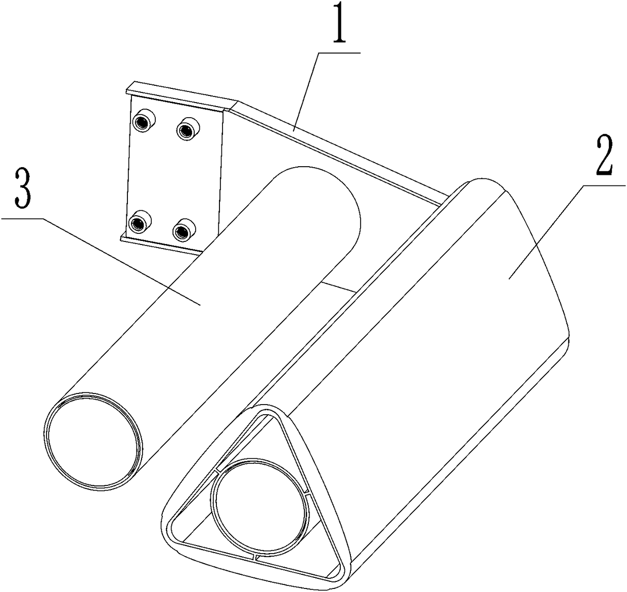
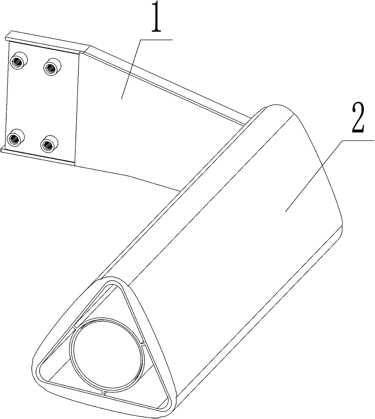
[0042] Such as Figure 4 Shown is a schematic isometric view of the mopping assembly in one of the preferred embodiments of the present invention. The technical characteristics of this preferred embodiment are mainly that the casing of the outer drum assembly 23 is in the shape of a triangular cylinder, and the liner 21 is an arc-shaped elastic structure distributed on each surface of the triangle, such as sponge, rubber and plastic foam, etc. Elastic material. Figure 4 The sleeve in the tube includes an external triangular cylindrical outer frame (not marked in the drawings), and a cylindrical inner frame (not marked in the drawings), the outer frame and the inner frame are fixed by several connection points, and the rest is hollow structure, the locking component is fixed on one side of the inner frame in the casing.
Embodiment 3
[0044] Such as figure 2 Shown is a schematic diagram of the isometric side view structure of one of the cantilever components of the present invention; image 3 A schematic diagram of the exploded structure of the structure is shown. The cantilever assembly 1 mainly includes an outer cover plate 11 , an arm plate 12 and an inner cover plate 13 arranged sequentially from outside to inside. Wherein, the outer edge of the outer cover plate 11 is provided with flanges for the limit arm plate 12 and the inner cover plate 13, and the two ends of the outer cover plate 11 are respectively provided with a number of positioning columns I 111 and positioning columns II 112 with internal threads. One end of the arm plate 12 is provided with a through hole I 121 corresponding to the position of the positioning column I 111 at one end, and the other end of the arm plate 12 is provided with threaded holes II 122 for installing the mopping assembly 2 and the storage assembly 3 respectively,...
PUM
 Abstract
Description
Claims
Application Information
 - R&D Engineer
- R&D Manager
- IP Professional
- Industry Leading Data Capabilities
- Powerful AI technology
- Patent DNA Extraction
Browse by: Latest US Patents, China's latest patents, Technical Efficacy Thesaurus, Application Domain, Technology Topic, Popular Technical Reports.
© 2024 PatSnap. All rights reserved.Legal|Privacy policy|Modern Slavery Act Transparency Statement|Sitemap|About US| Contact US: help@patsnap.com