
High precision imager

An imager and high-precision technology, applied in the field of high-precision imagers, can solve the problems affecting the accuracy of the Z-axis slide and the instability of the accuracy of the Z-axis slide

Pending Publication Date: 2018-07-24
东莞市骏智机电科技有限公司
View PDF0 Cites 1 Cited by
  • Summary
  • Abstract
  • Description
  • Claims
  • Application Information

AI Technical Summary

Problems solved by technology

[0003] When the image measuring instrument is used, the accuracy of the Z-axis slide is very important. In the prior art, when the Z-axis slide moves up and down, it is directly driven by the screw web, that is, the Z-axis slide is directly connected to the screw web or the Z-axis slide passes through The metal block is connected to the screw web, that is, it is rigidly connected, but when the screw web drives the Z-axis skateboard, there will be a slight deformation, and then the deformation will be transmitted to the Z-axis skateboard, which will affect the accuracy of the Z-axis skateboard when it moves up and down. How to reduce it? The influence of the web deformation of the screw rod on the Z-axis slide is a technical problem urgently needed to be solved by those skilled in the art
[0004] Moreover, in the prior art, slide rails and sliders are arranged between the Z-axis slide plate and the fixed plate, and the number of slide blocks is generally four or six, that is, there are four or six fixed points between the Z-axis slide plate and the fixed plate. Six, because only 3 points can form a surface, resulting in multiple connection surfaces between the Z-axis slide plate and the fixed plate, and due to the internal stress of the metal, the Z-axis slide plate will inevitably cause the Z-axis slide plate to go up and down due to the internal stress of the metal. Accuracy is unstable during exercise

Method used


Image

  • High precision imager
  • High precision imager
  • High precision imager

Examples


Embodiment Construction

[0025] The following will clearly and completely describe the technical solutions in the embodiments of the present invention with reference to the drawings in the embodiments of the present invention.

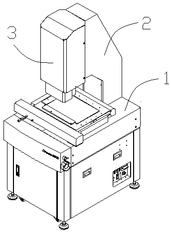
[0026] see Figure 1-4 and Figure 8 , a high-precision video instrument, comprising a body 1, a fixing frame 2 for fixing a head 3 is arranged on the body 1, the head 3 is arranged on the fixing frame 2, and the head 3 includes a fixed Plate 31, screw rod width 33 and Z-axis slide plate 36, the screw rod width 33 is driven by the drive motor 32, the two ends of the screw rod width 33 are fixed on the fixed plate 31, and the screw rod width 33 passes through The flexible connection mechanism 35 drives the Z-axis slide plate 36 to move vertically. The Z-axis slide plate 36 is provided with a vertically downward lens 37 .

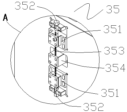
[0027] see Figure 5-6 , the flexible connection mechanism 35 includes a fixed block 351, a steel wire rope 353 and a connecting block 354, the fixed blo...


PUM


Abstract

The invention relates to a high precision imager, comprising a machine head; the machine head comprises a fixed plate, a screw rod frame and a Z-axis sliding plate, wherein the two ends of the screw rod frame are fixed on the fixed plate; the screw rod frame drives the Z-axis sliding plate to make vertical movement by means of a soft connecting mechanism. The high precision imager has the beneficial effects that the soft connecting mechanism comprises a fixed block, a steel wire rope and a connecting block; the connecting block is in non-contact with the Z-axis sliding plate; when the screw rod frame is deformed, the copper wire rope can absorb the deformation so as to prevent the deformation from being transmitted to the Z-axis sliding plate, so that the Z-axis sliding plate is enabled tobe closer to vertical, and the vertical accuracy of the Z-axis sliding plate is guaranteed. Due to the arrangement of three sliding blocks, only one connection surface is enabled to exist between theZ-axis sliding plate and the fixed plate, and the vertical precision of the Z-axis sliding plate is better guaranteed.

Description

technical field [0001] The invention relates to the field of image measurement, in particular to a high-precision image instrument. Background technique [0002] Imager, also known as image measuring instrument, is based on CCD digital images, relying on computer screen measurement technology and powerful software capabilities of spatial geometric calculations. After the computer is installed with special control and graphic measurement software, it becomes the measurement brain with the soul of the software, which is the main body of the whole device. It can quickly read the displacement value of the optical ruler, and obtain the desired result instantly through the calculation of the software module based on the space geometry; Possible deviations in measurement results. The image measuring instrument is a high-precision measuring instrument composed of a high-resolution CCD color lens, a continuous variable magnification objective lens, a color display, a video crosshai...

Claims


Application Information

Patent Timeline
Patent Type & Authority Applications(China)
IPC IPC(8): G01C11/00
CPCG01C11/00
Inventor 郑文英
Owner 东莞市骏智机电科技有限公司
Learn More