
Impeller and centrifugal compressor comprising same

A technology of centrifugal compressors and impellers, applied in mechanical equipment, machines/engines, liquid fuel engines, etc., can solve problems such as gap leakage loss, large flow channel eddy current loss, blades that are not easy to work with fluid, and small flow channel section height and width. Achieve the effects of reducing fluid leakage loss and eddy current loss, improving work efficiency, and large channel section aspect ratio

Pending Publication Date: 2018-07-24
天津快透平科技发展有限公司
View PDF0 Cites 1 Cited by
  • Summary
  • Abstract
  • Description
  • Claims
  • Application Information

AI Technical Summary

Problems solved by technology

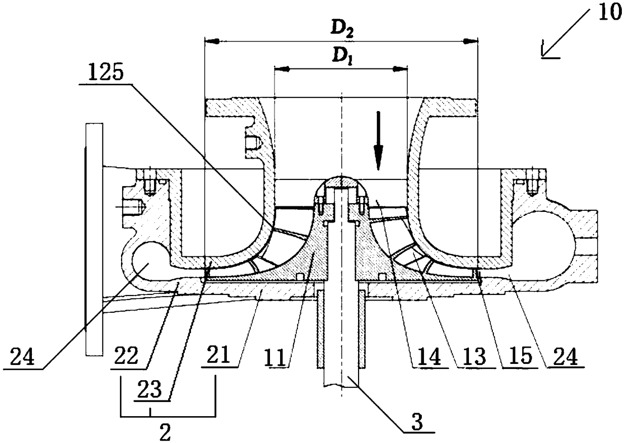
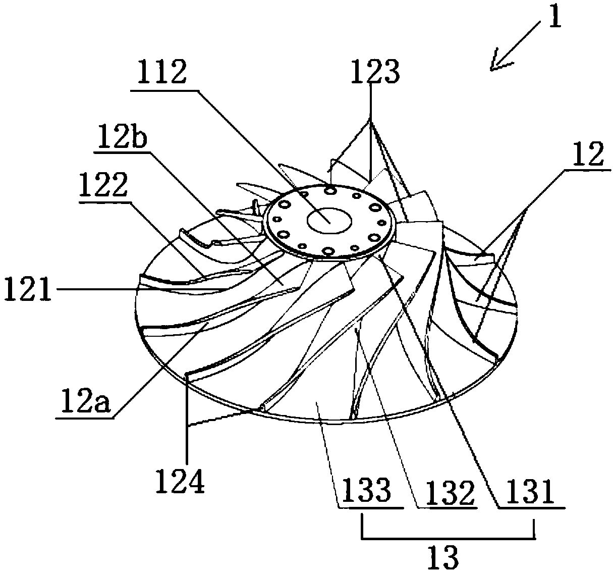
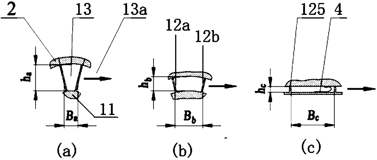
figure 2 and Figure 4 The existing compressor impeller shown (see below for the specific structure description) has the defect that the aspect ratio of the flow channel section is small, which makes it difficult for the blade to do work on the fluid, and the leakage loss in the gap between the blade tip and the casing and the flow channel The eddy current loss is large

Method used


Image

  • Impeller and centrifugal compressor comprising same
  • Impeller and centrifugal compressor comprising same
  • Impeller and centrifugal compressor comprising same

Examples


Embodiment 2

[0066] Both the pressure surface 12a and the suction surface 12b at the tail of the blade 12 in the second embodiment adopt a smooth streamlined curved surface and are combined at the trailing edge 124 to reduce the width of the blade at the outlet of the flow channel and form a narrow streamlined trailing edge to reduce the wake area, thereby reducing wake losses;

Embodiment 3

[0067] The blade of embodiment three is a hollow structure, that is, the part between the pressure surface sheet 12-1 and the suction surface sheet 12-2 of the blade is removed to form a hollow blade with a closed or bifurcated tail, so that the impeller has a lighter weight and better mechanical strength.

[0068] Compared with the prior art, the impeller of the present invention can work at a lower specific speed and has the following characteristics:

[0069] In the case of the same boost and flow rate, it has a lower physical speed;

[0070] In the case of the same flow rate and physical speed, it has a higher boost;

[0071] In the case of the same rotational speed and boost pressure, it can be applied to fluid compression with a smaller flow rate.

[0072] According to experiments, compared with the existing impeller, the impeller of the present invention can reduce the physical speed by 10%-30% under different working conditions under the same pressure boost and flow ...


PUM


Abstract

The invention provides an impeller and a centrifugal compressor comprising the same, and belongs to the technical field of centrifugal compression equipment. The impeller comprises a hub and a plurality of blades extending outsides along the peripheral curved surface of the hub, the blades are variable thickness blades, and on any runner cross sections in the length direction of the blades, the height of the blades is not smaller than the width of runners. According to the impeller and the centrifugal compressor comprising the same, the blades are the blades of which the thickness is graduallyincreased from leading edges to tailing edges or the blades that pressure surfaces and force suction surfaces at the tails of the blades are all smooth streamline curved surfaces and narrow streamline blade tailing edges are formed at the tailing edges of the blades; the impeller has the large runner cross section depth-width ratio; the thick part of the tail of each blade is of a hollow structure, and namely, pressure surface sheets and force suction surface sheets cross at the tailing edges and are connected together, or do not cross and are not connected together; and the impeller has thelarge runner cross section depth-width ratio, the small mass and the better mechanical strength. The impeller can work at a low specific speed and be suitable for compression of fluid with the smallerflow rate.

Description

technical field [0001] The invention belongs to the technical field of centrifugal compression equipment, and in particular relates to an impeller with a large aspect ratio flow passage section capable of reducing energy loss and a centrifugal compressor including the impeller. Background technique [0002] A centrifugal compressor is a fluid machine that converts mechanical energy into pressure energy, and is widely used in industrial fields. The main components of a centrifugal compressor are a high-speed rotating centrifugal impeller and a casing for accommodating the impeller. The casing expands outward to form a diffuser with a gradually increasing flow area. The flow formed by the diffuser and adjacent blades of the impeller The road is connected. The high-speed rotating centrifugal impeller does work on the fluid entering the flow channel of the impeller, making the fluid a high-pressure and high-speed fluid. The high-pressure and high-speed fluid flows out of the im...

Claims


Application Information

Patent Timeline
Patent Type & Authority Applications(China)
IPC IPC(8): F04D17/10F04D29/28F04D29/30
CPCF04D17/10F04D29/284F04D29/30F05D2240/304F05D2240/306F05D2240/305
Inventor 王晓宇国相杰刘建军
Owner 天津快透平科技发展有限公司
Learn More