
Limiting mechanism achieving rotary push-and-pull opening and closing on furniture

A technology for limiting mechanism and furniture, which is applied in the direction of building components, hinges with pins, and the arrangement of wing fans, etc., can solve the problems of inability to meet the needs of users, limited storage space in the cabinet, and injuries to users, and achieves improved horizontal Activities to open or close the storage effect, horizontal activities to open or close the storage smoothly, the effect of maximizing space utilization

Active Publication Date: 2018-07-24
GUANGDONG DTC HARDWARE PRECISION MFG CO LTD
View PDF7 Cites 2 Cited by
  • Summary
  • Abstract
  • Description
  • Claims
  • Application Information

AI Technical Summary

Problems solved by technology

However, the storage space of the cabinet part of this structure is limited, so it cannot be widely applied to large furniture cabinets. If the full-length mirror is designed to be larger, it will take up space, and the full-length mirror cannot be pushed into storage or pulled out to open it. As a result, the full-length mirror is easy to swing left and right due to the springback of the hinge or the habit of the original car, which will easily cause safety hazards such as damage to the full-length mirror or user injury when the user is using it, and cannot meet the needs of the user.

Method used


Image

  • Limiting mechanism achieving rotary push-and-pull opening and closing on furniture
  • Limiting mechanism achieving rotary push-and-pull opening and closing on furniture
  • Limiting mechanism achieving rotary push-and-pull opening and closing on furniture

Examples


Embodiment Construction

[0033] The present invention will be further described below in conjunction with the accompanying drawings and embodiments.

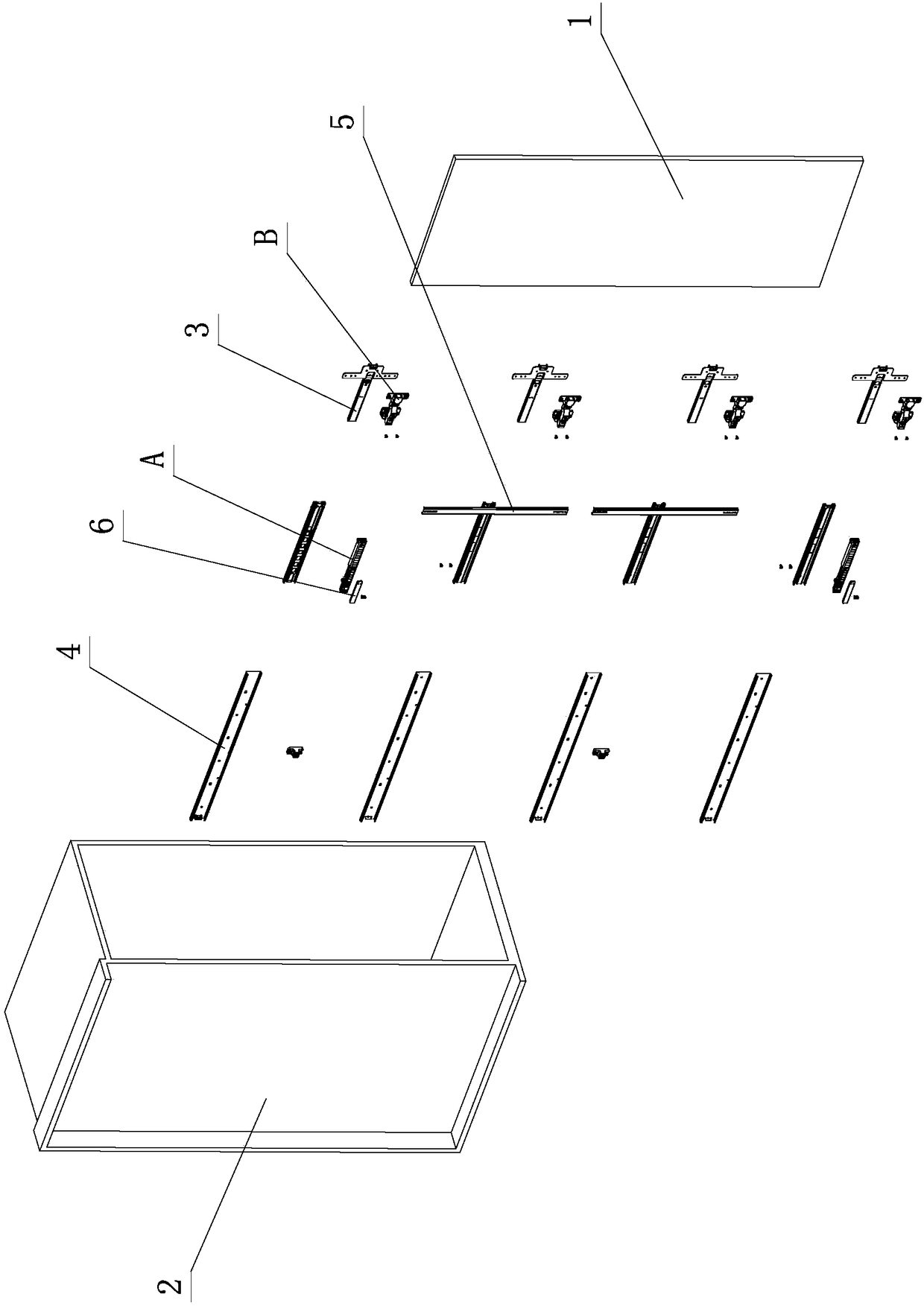
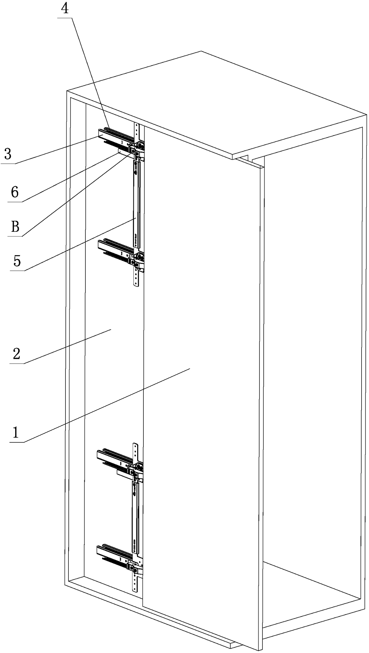
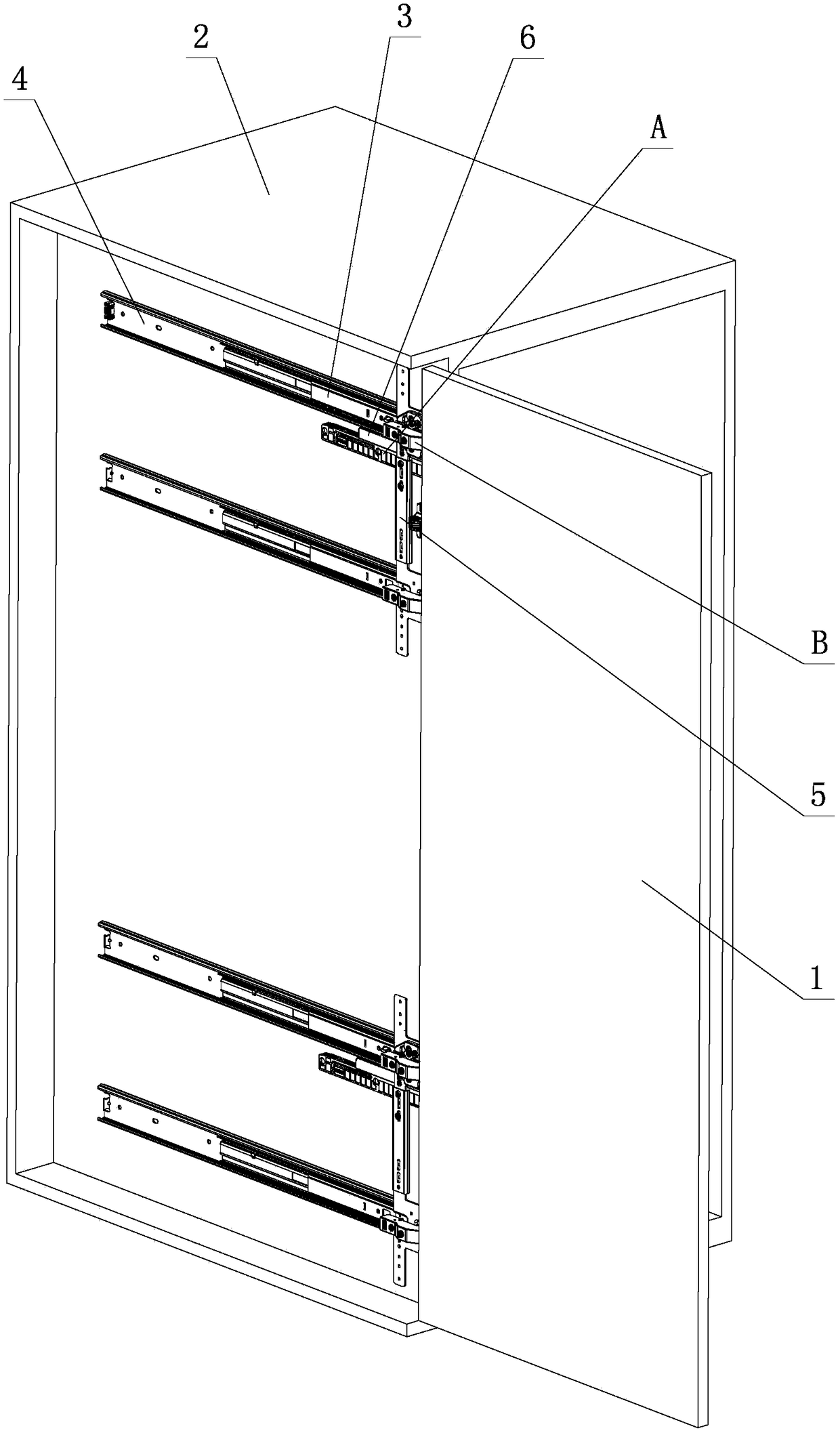
[0034] see Figure 1-Figure 8 , the limit mechanism of the rotary push-pull opening and closing furniture includes a furniture door body 1, a furniture cabinet body 2 and at least two slide rail assemblies. Balls or rollers are arranged between the slide rail 3 and the fixed slide rail 4, and the balls or rollers slide and cooperate with each other. At least two moving slide rails 3 are arranged on the furniture door body 1, and at least two fixed slide rails 4 are arranged on the furniture door body. On the side wall of the cabinet body 2, a synchronous rod 5 is arranged between at least two moving slide rails 3, and synchronously slides on at least two fixed slide rails 4 through the synchronous rod 5, so as to realize the lateral movable opening of the furniture door 1 and / or Or closed and stored on the furniture cabinet body 2, a horizontal opening...


PUM


Abstract

A limiting mechanism achieving rotary push-and-pull opening and closing on furniture comprises a furniture door body, a furniture cabinet body and at least two sliding rail assemblies. The at least two sliding rail assemblies at least comprise moving sliding rails and fixed sliding rails. Balls or rolling wheels are arranged between the moving sliding rails and the fixed sliding rails, and the moving sliding rails and the fixed sliding rails are in sliding fit through the balls or rolling wheels. The at least two moving sliding rails are arranged on the furniture door body, and the at least two fixed sliding rails are arranged on the side walls of the furniture cabinet body. Synchronous rods are arranged between the at least two moving sliding rails, and the at least two moving sliding rails synchronously slide on the at least two fixed sliding rails through the synchronous rods so that the furniture door body can be transversely and movably opened and / or closed to be stored on the furniture cabinet body. Transverse opening automatic locking devices are arranged between the side walls of the furniture cabinet body or between the fixed sliding rails and the moving sliding rails or between the synchronous rods. When the furniture door body is transversely and movably opened to a certain position relative to the furniture cabinet body, the movable opening position between the furniture door body and the furniture cabinet body is automatically locked through the transverse opening automatic locking devices, and practicality is high.

Description

technical field [0001] The invention relates to a limit mechanism for rotary push-pull opening and closing furniture. Background technique [0002] The Chinese patent literature number is CN2327260, which discloses a full-length mirror with a hidden storage cabinet on July 7, 1999. It has a cabinet part, and the rear wall and side walls of the cabinet form a space and a front opening. The door of the mirror cabinet is fixed on the cabinet with hidden hinges, and can cover the front opening of the cabinet, thus forming a mirror storage cabinet. When the cabinet door is closed, it is aligned with the cabinet, and it looks like a whole. The mirror storage cabinet is installed between two pillars on a base, and is rotatably fixed on the pillars so that the storage cabinet can be tilted. There is a tilt adjustment mechanism at a distance from the rotation point, which can adjust the relative position of the mirror storage cabinet. Based on the inclination angle of the support pi...

Claims


Application Information

Patent Timeline
Patent Type & Authority Applications(China)
IPC IPC(8): E05D13/00E05D15/06E05C17/60E05F5/06E06B3/50E05D7/04E05D3/06
CPCE05D3/06E05D7/0407E05D13/04E05D15/0621E05F5/06E06B3/5045E06B3/5054E05D2007/0492
Inventor 伍志勇
Owner GUANGDONG DTC HARDWARE PRECISION MFG CO LTD
Learn More