
Grouting sleeve assembly

A technology of grouting sleeves and components, which is applied in the direction of building components, building reinforcements, structural elements, etc., and can solve problems such as the inability to ensure the density of the grout in the sleeve, material waste, connection quality, and instability

Pending Publication Date: 2018-07-24
CHINA MINGSHENG DRAWIN TECH INVESTMENT CO LTD
View PDF5 Cites 6 Cited by
  • Summary
  • Abstract
  • Description
  • Claims
  • Application Information

AI Technical Summary

Problems solved by technology

[0003] In the prior art, the following problems exist in the sleeve grouting construction process: first, when the slurry overflows from the air outlet, it cannot be guaranteed that the slurry in the sleeve is dense
Therefore, there is a waste of grouting material in the current grouting process and the stability of the connection cannot be guaranteed; secondly, during the grouting construction process, the grout overflows from the air outlet, and there is a problem that the repeated sealing of the air outlet increases the construction complexity; thirdly, the grout is filled When the grouting pump is pulled out, the grout in the sleeve will flow back due to pressure, resulting in material waste and unstable connection quality

Method used


Image

  • Grouting sleeve assembly
  • Grouting sleeve assembly
  • Grouting sleeve assembly

Examples


Embodiment Construction

[0053] The present invention will be described in detail below in conjunction with the accompanying drawings. The description in this part is only exemplary and explanatory, and should not have any limiting effect on the protection scope of the present invention. In addition, those skilled in the art can make corresponding combinations of features in the embodiments in this document and in different embodiments according to the descriptions in this document.

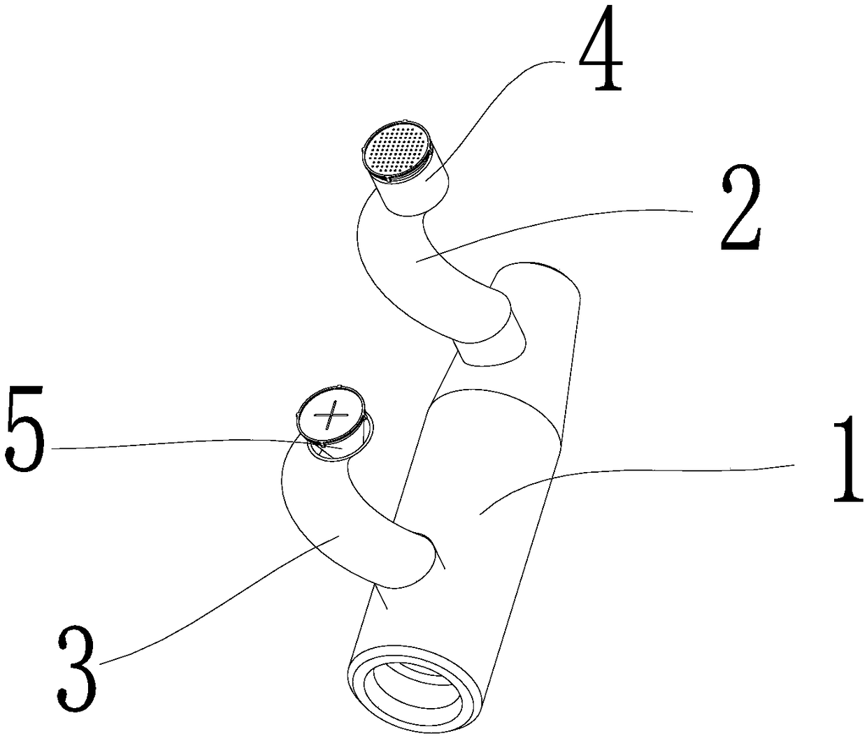
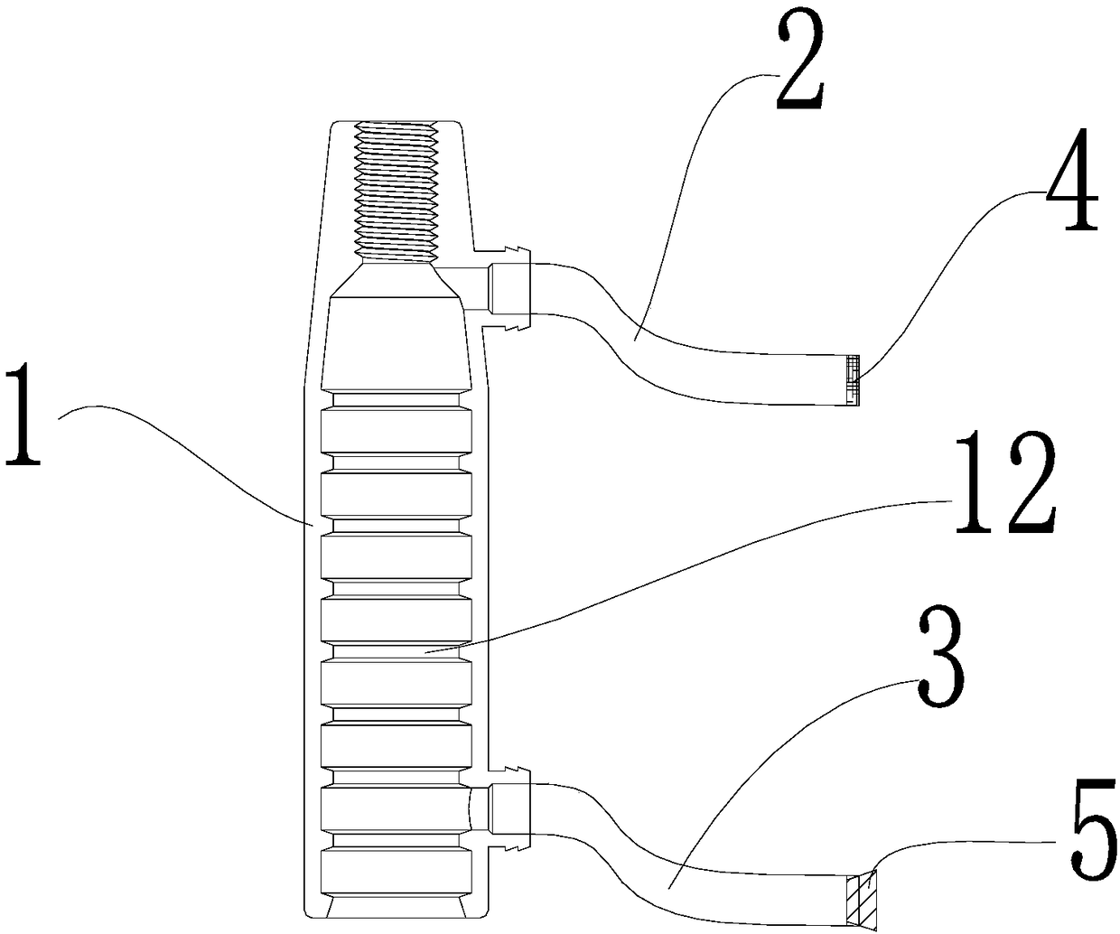
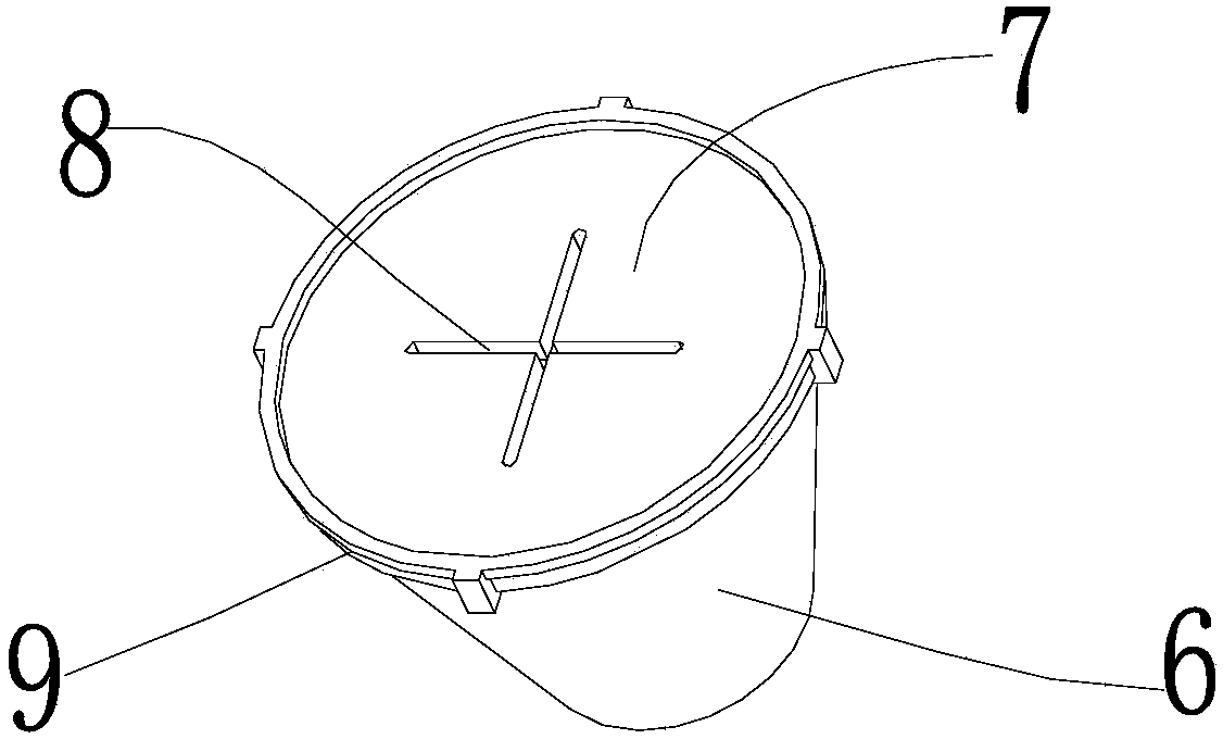
[0054] Embodiments of the present invention are as follows, with reference to figure 1 and figure 2 , a grouting sleeve assembly, including a sleeve body 1, an exhaust pipe 2 and a grouting pipe 3, the sleeve body 1 is provided with an exhaust hole and a grouting hole, and the exhaust pipe 2 and the grouting pipe 3 are respectively connected with the exhaust hole and the grouting hole, the exhaust port of the exhaust pipe 2 is provided with a ventilating sealing device 4 for preventing the grouting material from overfl...


PUM


Abstract

The invention belongs to the technical field of construction of building structures, and in particular relates to a grouting sleeve assembly. The grouting sleeve assembly comprises a sleeve body, an exhaust pipe and a grouting pipe, wherein the sleeve body is provided with an exhaust hole and a grouting hole; the exhaust pipe and the grouting pipe are respectively connected with the exhaust hole and the grouting hole; an air permeable plugging device used for preventing a grouting material from overflowing is arranged at the exhaust outlet of the exhaust pipe; a non-return device used for preventing backflow of the grouting material is arranged at a grouting mouth of the grouting pipe. In the grouting process, the air in the sleeve body can be smoothly discharged outside through the air permeable plugging device, and the air permeable plugging device provides pre-resistance so as to enable the interior of the grouting sleeve to be densely grouted; the air permeable plugging device canprevent the grouting material from overflowing when the sleeve is grouted or after the sleeve is fully grouted; after the sleeve is fully grouted, if the slurry in the sleeve body has a tendency to backflow, the non-return device can effectively block a grouting channel so as to prevent the slurry from backflowing; the grouting sleeve assembly guarantees dense grouting while achieving the aim of reducing waste, and also guarantees the connection performance.

Description

technical field [0001] The invention belongs to the technical field of building structure construction, and in particular relates to a grouting sleeve assembly. Background technique [0002] In the traditional cast-in-place concrete structure, the sleeve grouting connection of steel bars is widely used in the connection of longitudinal steel bars in the structure, and its performance is reliable under the premise of ensuring the construction quality. In the prior art, the steel bar connection between the prefabricated concrete building parts needs to be connected by sleeve grouting. The two connected steel bars are inserted into the metal sleeve and high-performance cement mortar is poured into the gap between the sleeve and the steel bar. After the cement mortar is hardened, the three are embedded with each other to realize the connection of the steel bars. [0003] In the prior art, the following problems exist in the sleeve grouting construction process: firstly, when th...

Claims


Application Information

Patent Timeline
IPC IPC(8): E04C5/16
CPCE04C5/165
Inventor 肖阿林唐雄易郴
Owner CHINA MINGSHENG DRAWIN TECH INVESTMENT CO LTD
Learn More