Laser guiding type robot charging pile

A laser-guided and robotic technology, applied in charging stations, electric vehicle charging technology, electric vehicles, etc., can solve the problems that the price of infrastructure construction affects the process of industrialization, does not form an economic scale, and the purchase price is relatively expensive. Unable to dock, fast and effective charging, and easy to use

Inactive Publication Date: 2018-07-24
CHENGDU ZHENGGUANG ELECTRONICS TECH CO LTD
View PDF0 Cites 0 Cited by
  • Summary
  • Abstract
  • Description
  • Claims
  • Application Information

AI Technical Summary

Problems solved by technology

[0002] For a robot powered by electric energy, the battery that can make it work is the key technology. At present, the energy stored in the unit weight of the battery is too little. At the same time, the battery used by the robot is relatively expensive and has not formed an economic scale. The purchase price also more expensive
Therefore, for robots, the biggest obstacle at present is that infrastructure construction and prices affect the process of industrialization
When the robot is running, because its battery is pre-configured, it is likely to consume the power in the battery when it is working. If there is no corresponding charging station for the robot to directly charge the robot quickly and effectively, the long-term work of the robot will be difficult. impossible to become a reality

Method used


Image

  • Laser guiding type robot charging pile
  • Laser guiding type robot charging pile
  • Laser guiding type robot charging pile

Examples


Embodiment Construction

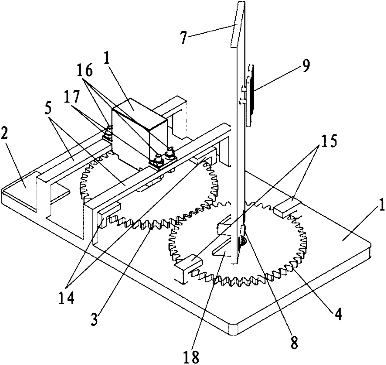
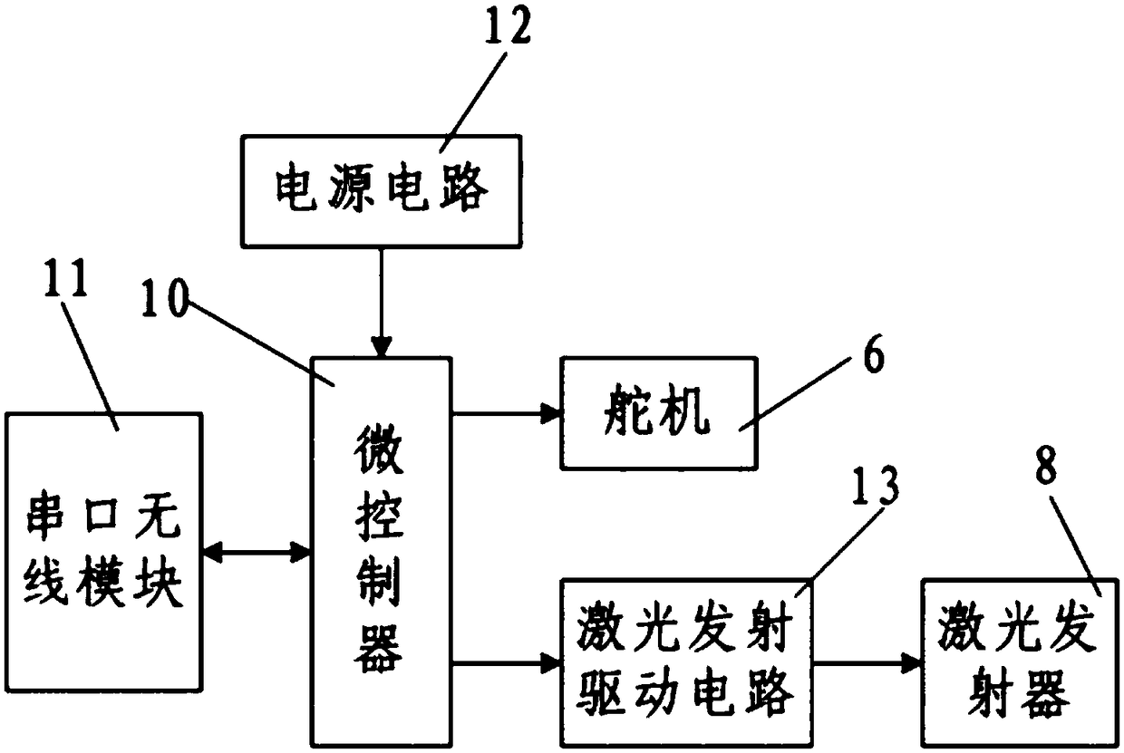
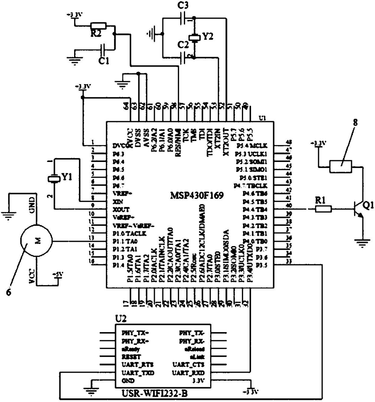
[0031] like figure 1 As shown, the present invention includes a base 1 and a laser guide control circuit board 2 installed on the base 1, and a first gear 3 and a second gear 4 that are rotatably connected to the base 1 and engaged with each other, and the base 1 is passed through the rudder The machine bracket is fixedly connected with a steering gear 6 located above the first gear 3, the first gear 3 is fixedly connected with the output shaft of the steering gear 6, and the second gear 4 is fixedly connected with a power insertion baffle 7, the The bottom of the power supply insertion baffle 7 is fixedly connected with the laser transmitter 8 used in conjunction with the laser receiver installed on the robot, and the top of the power insertion baffle 7 is fixedly connected with a power socket 9 connected to the mains; The laser guidance control circuit board 2 is integrated with a laser guidance control circuit, combined with figure 2 , the laser guidance control circuit i...


PUM


Abstract

The invention discloses a laser guiding type robot charging pile, comprising a base and a laser guiding control circuit board mounted on the base, as well as a first gear and a second gear which are meshed mutually and rotatably connected to the base. The base is fixedly connected with a steering gear located above the first gear through a steering gear bracket. The first gear is fixedly connectedwith the output shaft of the steering gear. The second gear is fixedly connected with a power supply insertion baffle. The lower part of the power supply insertion baffle is fixedly connected with alaser transmitter. The upper part of the power supply insertion baffle is fixedly connected with a power supply socket. A laser guiding control circuit is integrated on the laser guiding control circuit board. The laser guiding control circuit comprises a microcontroller, a serial port wireless module, a power supply circuit and a laser emitting driving circuit. The laser guiding type robot charging pile has the advantages of being simple in structure, small in size, convenient to implement, low in cost, convenient to use, capable of quickly and effectively charging a robot battery, high in practicability, good in use effect, and convenient to popularize and use.

Description

technical field [0001] The invention belongs to the technical field of robot autonomous charging, and in particular relates to a laser-guided robot charging pile. Background technique [0002] For a robot powered by electric energy, the battery that can make it work is the key technology. At present, the energy stored in the unit weight of the battery is too little. At the same time, the battery used by the robot is relatively expensive and has not formed an economic scale. The purchase price Also more expensive. Therefore, for robots, the biggest obstacle at present is that infrastructure construction and prices affect the process of industrialization. When the robot is running, because its battery is pre-configured, it is likely to consume the power in the battery when it is working. If there is no corresponding charging station for the robot to directly charge the robot quickly and effectively, the long-term work of the robot will be difficult. Impossible to become a re...

Claims


Application Information

Patent Timeline
Patent Type & Authority Applications(China)
IPC IPC(8): B60L11/18
CPCB60L53/35B60L53/37Y02T10/70Y02T10/7072Y02T90/12Y02T90/16
Inventor 不公告发明人
Owner CHENGDU ZHENGGUANG ELECTRONICS TECH CO LTD
Why Eureka
Try Eureka