
Cutting equipment for coating composite fabric

A composite fabric and coating technology, applied in welding equipment, laser welding equipment, metal processing equipment, etc., can solve the problem that heat and smoke cannot be handled well, equipment operation cannot be stopped in time, and loose edge wires are prone to appear and other problems, to achieve the effects of reducing economic losses and personnel safety hazards, facilitating troubleshooting, and convenient operation

Inactive Publication Date: 2018-07-24
HAINING JIESHENG NEW MATERIAL
View PDF5 Cites 1 Cited by
  • Summary
  • Abstract
  • Description
  • Claims
  • Application Information

AI Technical Summary

Problems solved by technology

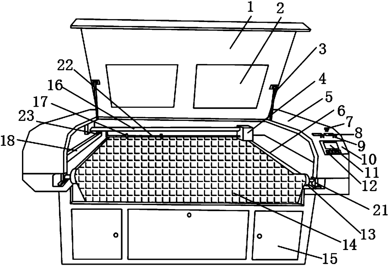
[0002] The fabric cutting equipment is specially made for the garment industry and the cutting of plush fabrics. It can accurately cut any pattern of various clothing fabrics. It can be equipped with a feeding device to realize continuous and automatic cutting of roll materials, making it convenient and fast to receive and send materials, and cut fabrics. Including a variety of materials, it can be used with the clothing photo copying machine to quickly make samples; the existing fabric cutting equipment has certain disadvantages in use, and it is easy to have loose edges due to the influence of the knife edge, which increases the production cost. Moreover, the heat and smoke generated during the cutting process cannot be handled well, causing damage to the equipment and air pollution, and the operation of the equipment cannot be stopped in time when an emergency occurs, which has brought a certain impact on the user. For this reason, We propose a cutting device for coated composite fabrics

Method used


Image

  • Cutting equipment for coating composite fabric
  • Cutting equipment for coating composite fabric
  • Cutting equipment for coating composite fabric

Examples


Embodiment Construction

[0017] In order to make the technical means, creative features, goals and effects achieved by the present invention easy to understand, the present invention will be further described below in conjunction with specific embodiments.

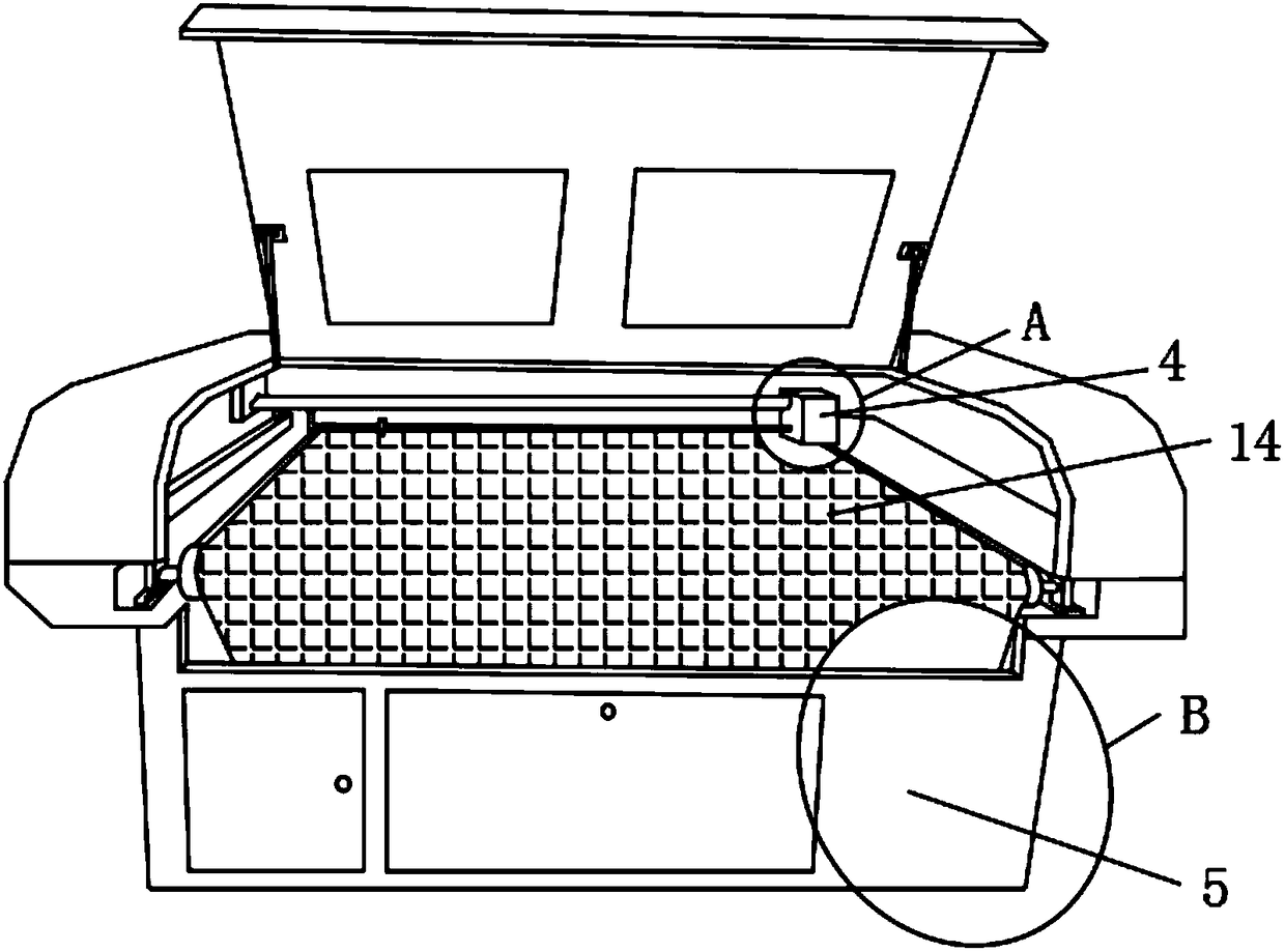
[0018] Such as Figure 1-4 As shown, a cutting device for coated composite fabrics includes a main body 5 and a motor 4. A storage door 15 is movably installed on the front outer surface of the main body 5 near the edge, and the front outer surface of the main body 5 is close to the storage door. 15 is provided with a control panel 10, the front outer surface of the control panel 10 is provided with a display screen 11, and the front end outer surface of the control panel 10 is provided with a function key 12 at the position below the display screen 11, and the upper end of the main body 5 A control knob 9 is arranged on the outer surface close to the control panel 10, and a scale 8 is arranged on the upper outer surface of the main body 5 near th...


PUM


Abstract

The invention discloses cutting equipment for coating composite fabric. The equipment comprises a main body and a motor. A storage door is movably installed at the position, close to the edge, of theouter surface of the front end of the main body. A control panel is arranged at the position of the side, close to the storage door, of the outer surface of the front end of the main body. A display screen is arranged on the outer surface of the front end of the control panel, a function key is arranged at the position below the display screen on the outer surface of the front end of the control panel, a control rotary knob is arranged at the position, close to the control panel, of the outer surface of the upper end of the main body, and a dial gauge is arranged at the position, close to therear end of the control rotary knob, of the outer surface of the upper end of the main body. According to the cutting equipment for the coating composite fabric, a brake and a fan are arranged, economic losses and personnel safety hazards caused in emergency circumstances are reduced, damage to the equipment and harm to personnel caused by heat and smoke dust are reduced, the functionality is effectively improved, and a better using prospect is brought.

Description

technical field [0001] The invention relates to the field of cutting equipment, in particular to a cutting equipment for coated composite fabrics. Background technique [0002] The fabric cutting equipment is specially made for the garment industry and plush fabric cutting. It can accurately cut any pattern of various clothing fabrics. It can be equipped with a feeding device to realize continuous and automatic cutting of roll materials, making it convenient and fast to receive and send materials, and cutting fabrics Including a variety of materials, it can be used with the clothing photo copying machine to quickly make samples; the existing fabric cutting equipment has certain disadvantages in use, and it is easy to have loose edges due to the influence of the knife edge, which increases the production cost. Moreover, the heat and smoke generated during the cutting process cannot be handled well, causing damage to the equipment and air pollution, and the operation of the eq...

Claims


Application Information

Patent Timeline
IPC IPC(8): B23K26/38B23K26/70
CPCB23K26/38B23K26/70B23K26/702
Inventor 马耀祥
Owner HAINING JIESHENG NEW MATERIAL
Learn More