Die-casting machine for plug-and-socket fasteners

A technology of die-casting machine and buckle, which is applied in the field of molding equipment, can solve the problems of wasting materials and processing man-hours, low processing efficiency, complex processing technology, etc., and achieve the effect of improving pulling force, simple structure, and smooth left and right movement

Inactive Publication Date: 2018-07-24
DONGGUAN UNIV OF TECH
View PDF0 Cites 3 Cited by
  • Summary
  • Abstract
  • Description
  • Claims
  • Application Information

AI Technical Summary

Problems solved by technology

[0002] In daily necessities, fasteners are widely used. Notebooks, backpacks, etc. will be applied to fasteners. Among them, plug-in fasteners are the most widely used. Most of these fasteners are metal products, and their structures are mostly as Figure 8 As shown, including the main body 41, the side end of the main body is provided with a jaw 402 for cooperating with entrainment, and a threaded hole 43 is provided on the upper plate of the jaw, and the other end of the main body 41 is provided with a sleeve 44, and the sleeve corresponds to The position of the buckle plate 45 is set, and some fasteners also have a magnetic block mouth 46 for installing the magnetic block on the main body 41. For the processing of this type of fastener, most of the main body is first cast and then the sleeve and The processing of the jaw, the processing technology is complicated, and the material and processing time are wasted, resulting in low processing efficiency

Method used


Image

  • Die-casting machine for plug-and-socket fasteners
  • Die-casting machine for plug-and-socket fasteners
  • Die-casting machine for plug-and-socket fasteners

Examples


Embodiment Construction

[0032] In order to enable those skilled in the art to better understand the technical solution of the present invention, the present invention will be described in detail below in conjunction with the accompanying drawings. The description in this part is only exemplary and explanatory, and should not have any limiting effect on the protection scope of the present invention. .

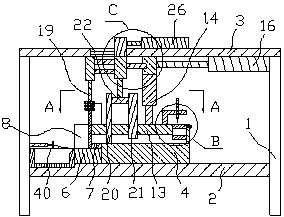
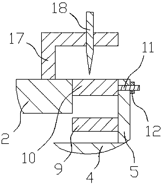
[0033] like Figure 1-Figure 8 As shown, the specific structure of the present invention is: a die-casting machine for socket fasteners, including a frame 1, the frame 1 is provided with a lower working plate 2 and an upper working plate 3, and the lower working plate 2 is provided with a lower module with side plates on the front and rear right sides, the inner side of the right side plate of the lower module is provided with a jaw forming block 9 and a jaw forming cover plate 10, and the lower part of the upper working plate 3 is provided with a A briquetting lifting cylinder 14, the upper mold briq...


PUM


Abstract

The invention relates to a die-casting machine for plug-and-socket fasteners. The die-casting machine comprises a machine frame; a lower working plate and an upper working plate are arranged on the machine frame; the lower working plate is provided with a lower module, and side plates are arranged on the front side, the rear side and the right side of the lower module; a clamping opening forming block and a clamping opening forming cover plate are arranged on the inner side of the right side plate of the lower module; a pressing block lifting cylinder is arranged below the upper working plate;the lower portion of the pressing block lifting cylinder is connected with an upper mold pressing block matched with the lower module; the left end of the upper mold pressing block is arc, and buckleplate forming openings are formed in the lower portions of the front side and the rear side of the left end; a socket opening forming column is arranged on the upper mold pressing plate and located between the two buckle plate forming openings in a penetrating and inserting fit mode; the upper end of the socket opening forming column is connected with a socket opening forming lifting block; the upper portion of the socket opening forming lifting block is connected with a socket opening forming lifting cylinder which is matched with a mold unloading movable device on the upper working plate; and the upper working plate is further provided with a side mold device in arc fit with the left end of the upper mold pressing block. By means of the die-casting machine, lateral mold-loading can be achieved, and the fastener machining efficiency is improved significantly.

Description

technical field [0001] The invention relates to the field of molding equipment, in particular to a die-casting machine for sleeve fasteners. Background technique [0002] In daily necessities, fasteners are widely used. Notebooks, backpacks, etc. will be applied to fasteners. Among them, plug-in fasteners are the most widely used. Most of these fasteners are metal products, and their structures are mostly as Figure 8 As shown, including the main body 41, the side end of the main body is provided with a jaw 402 for cooperating with entrainment, and a threaded hole 43 is provided on the upper plate of the jaw, and the other end of the main body 41 is provided with a sleeve 44, and the sleeve corresponds to The position of the buckle plate 45 is set, and some fasteners also have a magnetic block mouth 46 for installing the magnetic block on the main body 41. For the processing of this type of fastener, most of the main body is first cast and then the sleeve and The processing ...

Claims


Application Information

Patent Timeline
Patent Type & Authority Applications(China)
IPC IPC(8): B22D17/22B22D17/20B22D17/26
CPCB22D17/22B22D17/20B22D17/26
Inventor 谢春晓郑东海钟守炎
Owner DONGGUAN UNIV OF TECH
Why Eureka
Try Eureka