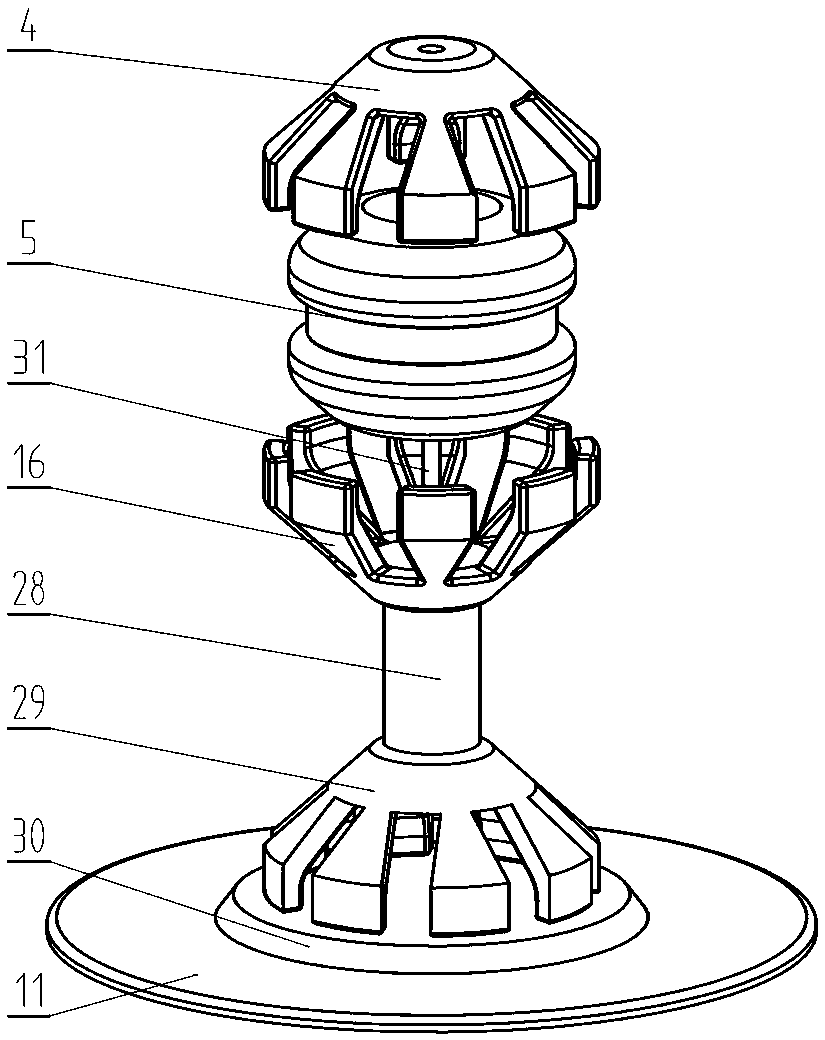
Knitting machine used for integrated formation of cylindrical braided fabric
A cylindrical braid and braiding machine technology, applied in the field of braiding machines, can solve the problems of imperfect processing, affect the appearance, easy to crack, etc., and achieve the effects of shortening production time, improving efficiency and quality, and increasing output
- Summary
- Abstract
- Description
- Claims
- Application Information
AI Technical Summary
Problems solved by technology
Method used
Image
Examples
Embodiment 1
[0037] Embodiment 1: A knitting machine for integrally forming cylindrical braids, comprising a base 11, an outer fixed ring body 12 and an inner fixed ring body 27 arranged in parallel with it are installed above the base 11, and the inner fixed ring body The body 27 is located inside the outer fixed ring body 12 and is coaxial with the outer fixed ring body 12; the inner fixed ring body 27 and the outer fixed ring body 12 are connected to the base 11 through the guide rod 10; the inner fixed ring body 27 corresponds to The position of the base 11 is provided with an inner jacking oil cylinder 13, and the top of the inner jacking oil cylinder 13 is connected with the inner fixed ring body 27; The top of the jacking cylinder 14 is connected to the outer fixed ring body 12; the inner fixed ring body 27 is distributed with a number of equally spaced inner wire feeding rods 20, and the top of the inner wire feeding rods 20 is provided with a penetrating inner wire feeding rod. Th...
Embodiment 2
[0038]Embodiment 2: A knitting machine for integral molding of cylindrical braids, wherein the weaving device includes a shuttle box 35 with a thread opening 34, and the top of the shuttle box 35 is a shuttle upper cover body 33, in the inside of the shuttle box body 35, a pay-off shaft 37 is installed by a bearing, and two disk-shaped bobbin stop plates 38 are symmetrically arranged on the pay-off shaft 37, and the shuttle box at the corresponding position of the stop plate 38 An elastic plate body 39 is installed on the body 35, and the free end of the elastic plate body 39 is in contact with the shuttle box body 35; the pay-off shaft 37 is wound with a wire harness at a position between two adjacent bobbin limiting plates 38; A contact wheel 36 is installed on the lower end surface of the shuttle box body 35, and the contact wheel 36 is connected with the drive motor. The track 17 is a ring structure with a U-shaped longitudinal section. Track side openings 25 are processed...
PUM
 Abstract
Description
Claims
Application Information
 - R&D
- Intellectual Property
- Life Sciences
- Materials
- Tech Scout
- Unparalleled Data Quality
- Higher Quality Content
- 60% Fewer Hallucinations
Browse by: Latest US Patents, China's latest patents, Technical Efficacy Thesaurus, Application Domain, Technology Topic, Popular Technical Reports.
© 2025 PatSnap. All rights reserved.Legal|Privacy policy|Modern Slavery Act Transparency Statement|Sitemap|About US| Contact US: help@patsnap.com


