
Wall breaking device for bee pollen production

A technology of bee pollen and protective shell, which is applied in the field of wall-breaking devices for bee pollen production, which can solve problems such as low wall-breaking efficiency, rising temperature of the wall-breaking machine, and poor quality of bee pollen wall-breaking, so as to improve the quality of wall-breaking, The effect of improving the breaking efficiency

Inactive Publication Date: 2018-07-24
湖州语纳蜂产品有限公司
View PDF0 Cites 0 Cited by
  • Summary
  • Abstract
  • Description
  • Claims
  • Application Information

AI Technical Summary

Problems solved by technology

[0002] The pollen wall usually has two layers, the inner wall and the outer wall. Since the pollen has a hard outer wall that is acid-resistant, alkali-resistant, and corrosion-resistant, it is necessary to remove impurities and sieve when processing cosmetics and other externally applied products and infant pollen food. After the bee pollen is broken, when the bee pollen is broken, the breaker in the existing technology is mainly completed by physical breaking, and the bee pollen has an effect on the internal temperature of the breaker when breaking the wall. Higher requirements, but when using a wall breaking machine to break the wall, it is easy to increase the internal temperature of the wall breaking machine, which makes the quality of bee pollen breaking the wall poor. In addition, the existing wall breaking machine has only one breaking head , low breaking efficiency

Method used


Image

  • Wall breaking device for bee pollen production
  • Wall breaking device for bee pollen production
  • Wall breaking device for bee pollen production

Examples


Embodiment Construction

[0020] In describing the present invention, it should be understood that the terms "center", "longitudinal", "transverse", "upper", "lower", "front", "rear", "left", "right", " The orientations or positional relationships indicated by "vertical", "horizontal", "top", "bottom", "inner" and "outer" are based on the orientations or positional relationships shown in the drawings, and are only for the convenience of describing the present invention and Simplified descriptions, rather than indicating or implying that the device or element referred to must have a particular orientation, be constructed and operate in a particular orientation, and thus should not be construed as limiting the invention. In addition, the terms "first", "second", etc. are used for descriptive purposes only, and should not be understood as indicating or implying relative importance or implicitly specifying the quantity of the indicated technical features. Thus, a feature defined as "first", "second", etc. ...


PUM


Abstract

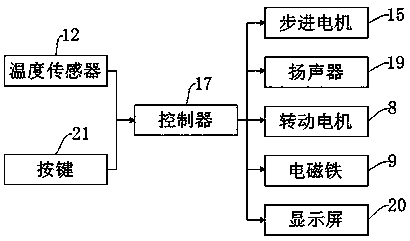
The invention discloses a wall breaking device for bee pollen production. The device comprises a bottom plate, a rotational shaft, a refrigeration plate and a stepping motor, a protection shell is arranged above the bottom plate, one side of the protection shell is provided with a first support frame, the other side of the protection shell is provided with a second support frame, a rear part of the protection shell is provided with an electromagnet, the protection shell is internally provided with a rotational motor, a shell is arranged above the protection shell, the shell is internally provided with the rotational shaft, a first wall breaking tool bit is arranged above the rotational shaft, and a second wall breaking tool bit is arranged below the first wall breaking tool bit. The wall breaking device has the beneficial effects that temperature inside the shell can be monitored through a temperature sensor, the refrigeration plate can be used for enabling the temperature inside the shell to be lowered, the wall breaking quality of the bee pollen is improved, and by operation through two wall breaking tool bits, the wall breaking efficiency of the bee pollen is improved.

Description

technical field [0001] The invention relates to the field of bee pollen production equipment, in particular to a wall breaking device for bee pollen production. Background technique [0002] The pollen wall usually has two layers, the inner wall and the outer wall. Since the pollen has a hard outer wall that is acid-resistant, alkali-resistant, and corrosion-resistant, it is necessary to remove impurities and sieve when processing cosmetics and other externally applied products and infant pollen food. After the bee pollen is broken, when the bee pollen is broken, the breaker in the existing technology is mainly completed by physical breaking, and the bee pollen has an effect on the internal temperature of the breaker when breaking the wall. Higher requirements, but when using a wall breaking machine to break the wall, it is easy to increase the internal temperature of the wall breaking machine, which makes the quality of bee pollen breaking the wall poor. In addition, the ex...

Claims


Application Information

Patent Timeline
IPC IPC(8): B02C18/12B02C18/16B02C25/00A23L21/20
CPCB02C18/12A23L21/20B02C18/16B02C25/00
Inventor 陆群芳
Owner 湖州语纳蜂产品有限公司
Learn More