Fume removal device for asphalt road maintenance vehicle

A technology for maintaining vehicles and roads. It is applied in the fields of combined devices, gas treatment, membrane technology, etc., and can solve the problems of asphalt organic matter that cannot be filtered and treated cleanly, and that there is no good treatment method.

Pending Publication Date: 2018-07-24
JIANGSU JITRI ROAD ENG TECH & EQUIP RES INST CO LTD
View PDF12 Cites 5 Cited by
  • Summary
  • Abstract
  • Description
  • Claims
  • Application Information

AI Technical Summary

Problems solved by technology

[0004] However, asphalt polluted organic matter cannot be filtered and treated, and there is no good treatment method for trace organic matter with a particle size of 0.01um-0.1um

Method used


Image

  • Fume removal device for asphalt road maintenance vehicle

Examples


Embodiment Construction

[0017] Below in conjunction with accompanying drawing and embodiment the patent of the present invention is described further.

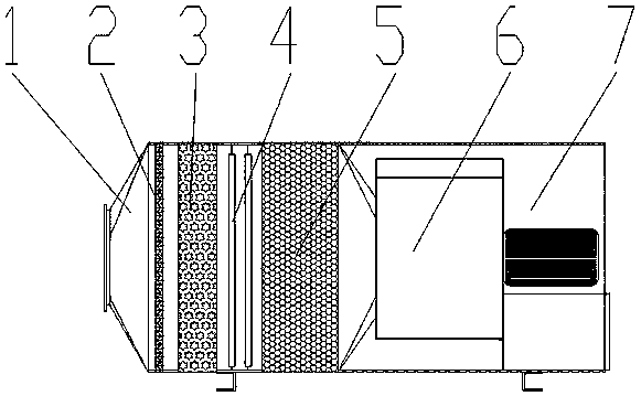
[0018] like figure 1 As shown, the function of the smoke removal equipment is mainly used to remove the asphalt fume VOCs organic pollutants generated by the asphalt road maintenance vehicle when heating the ground. The smoke removal equipment includes a filter tube 1, a settling plate 2, a Raschig ring defogging plate 3, a UV photolytic oxidation tube 4, and an activated carbon adsorption chamber 5 arranged sequentially inside the filter tube 1 along the inlet end to the gas outlet end. The air outlet is connected with the induced draft fan 6. The inlet end of the filter pipe 1 faces the position where the smoke is emitted or is connected to the structure that emits the smoke. The settling plate 2 is mainly used to settle large particles of dust and large particles of asphalt oil clusters. The Raschig ring defogging plate 3 is mainly used to remove...


PUM


Abstract

The invention discloses a fume removal device for an asphalt road maintenance vehicle. The fume removal device for the asphalt road maintenance vehicle comprises a filter pipe, wherein a settlement plate, a Raschig ring demisting plate, a UV (ultraviolet) photolysis oxidation pipe and an activated carbon adsorption cavity are sequentially arranged in the filter pipe from an air inlet end to an airoutlet end. An asphalt fume is filtered through the Raschig ring demisting plate, photolyzed through VOCs (Volatile Organic Chemicals) and adsorbed through activated carbon, so that a heating processof the fume removal device configured for a heating wall of the asphalt road maintenance vehicle is free of pollution, and the treated fume can meet the requirement of a national environmental standard.

Description

technical field [0001] The patent of the invention relates to a kind of smoke removal equipment for asphalt road maintenance vehicles, in particular to a kind of asphalt smoke treatment equipment. Background technique [0002] The flue gas produced by asphalt road construction equipment has been paid more and more attention by people. Its composition is extremely complex and varies with the source of asphalt. The main components are carbocyclic hydrocarbons, derivatives of cyclohydrocarbons and other compounds, which are harmful to human health. [0003] Conventional treatment of dust enters the purifier through the negative pressure generated by the fan through the side exhaust port and the lower exhaust port. After the dusty gas enters the filter cartridge dust collector through the air inlet, the airflow speed slows down due to the sudden increase of the cross-sectional area, and the coarse Particle dust breaks away from the airflow and settles into the dust collection ch...

Claims


Application Information

Patent Timeline
Patent Type & Authority Applications(China)
IPC IPC(8): B01D50/00B01D53/72B01D53/74
CPCB01D53/72B01D53/74B01D2258/0283B01D2257/708B01D50/20
Inventor 漆建平王贵张陈李家春李骁斐燕铎吴振毅樊丽丽成九瑞邓琅
Owner JIANGSU JITRI ROAD ENG TECH & EQUIP RES INST CO LTD
Why Eureka
Try Eureka