
Anti-blocking filtering basin and working method thereof

A filter tank and filter technology, applied in the direction of filtration separation, separation method, filtration circuit, etc., can solve the problems of inability to distribute and filter silt, difficult operation, filter clogging, etc., to reduce the possibility of system fouling and simplify operation Effect of maintenance process, reduction of burden and loss

Pending Publication Date: 2018-07-20
麦菲特水务(广东)有限公司
View PDF0 Cites 0 Cited by
  • Summary
  • Abstract
  • Description
  • Claims
  • Application Information

AI Technical Summary

Problems solved by technology

[0003] In the traditional sewage treatment system, the sedimentation and sedimentation of the sedimentation tank are indispensable parts. At the same time, it occupies a large area and directly increases the investment of the factory, and the fixed design water volume determines that it cannot accept large fluctuations in the water volume. The swelling of the sludge and the flocculation effect of the influent also directly affect the water quality of the effluent
[0004] Existing filtration equipment generally needs to create a pressure difference, and making a pressure difference requires more energy consumption
The filter device is prone to the problem of filter clogging, and too many impurities can easily block the filter holes, thereby affecting the filtering effect; the existing solutions cannot solve the problem of clogging well, and the operation is difficult, resulting in higher filtration costs
[0005] The existing technology is not targeted enough, and cannot distribute and filter the sludge of different particle sizes, resulting in a short service life of the filter device and easy damage to the filter element
Or the structure of the equipment is complex and the cost of use is high
At the same time, the existing equipment occupies a large area and consumes a lot of energy

Method used


Image

  • Anti-blocking filtering basin and working method thereof
  • Anti-blocking filtering basin and working method thereof

Examples


Embodiment Construction

[0038] The present invention will be further described below in conjunction with accompanying drawing:

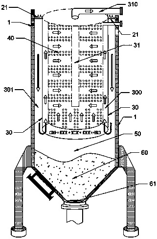
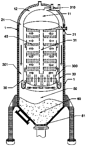
[0039] An anti-clogging filter tank, comprising a filter tank 1; the inside of the filter tank 1 is provided with a flow direction partition cover 30;

[0040] The space between the flow partition cover 30 and the filter tank 1 is a water flow down channel 301, and the upper part of the water flow down channel 301 is provided with a water inlet 21;

[0041] A filter 40 is provided in the flow partition cover 30 , and an opening is provided at the bottom of the flow partition cover 30 ; the space between the side wall of the partition cover 30 and the filter 40 is a water flow upward channel 300 ;

[0042] The inside of the filter 40 is a water collection channel 31, and the water collection channel 31 communicates with the outside of the filter tank 1 through the water production pipe 310;

[0043] The bottom of the filter tank 1 is a sludge collection area 60, and the bot...


PUM


Abstract

The invention provides an anti-blocking filtering basin and a working method thereof. The anti-blocking filtering basin comprises a filtering basin. A flow direction partition cover is arranged in thefiltering basin. The interval space of the flow direction partition cover and the filtering basin is a current down channel, and a water inlet is formed in the upper portion of the current down channel. A filter is arranged in the flow direction partition cover, and an opening is formed in the bottom of the flow direction partition cover. The interval space of the side wall of the partition coverand the filter is a current up channel. A water collecting channel is formed in the filter and communicated with the exterior of the filtering basin through a water producing pipe. The anti-blockingfiltering basin has the advantages that the filter is flushed by bubbles generated by an air distributing device, meanwhile, the filter swings in water through decrease of the water level, and the filter is further flushed; the effects of gravity and buoyancy are fully utilized, and incoming flocculating water is automatically divided into high-turbidity currents and low-turbidity currents; large-particle sludge is directly separated, the load and losses of the filter are reduced accordingly, and a settling pond and a sand filter can be replaced at the same time.

Description

technical field [0001] The invention belongs to the field of sewage treatment, and in particular relates to an anti-clogging filtering device and a working method. Background technique [0002] In urban sanitation work, it is necessary to regularly remove garbage, sludge, etc. in the sewer to ensure the smooth flow of the sewer. With the rapid development of urban construction in our country, the length of urban sewers has also increased rapidly, and the dredging work of sewers has become more and more arduous. The composition of sewage sludge is complex. In addition to containing a large amount of water, it also contains a large amount of organic matter, refractory organic matter, various trace elements, pathogenic microorganisms and parasite eggs, heavy metals and salts. The harmless and resource utilization of complex urban sewer sludge has become a new difficulty and challenge in the comprehensive environmental management work. [0003] In the traditional sewage treatm...

Claims


Application Information

Patent Timeline
IPC IPC(8): B01D36/04B01D35/16
CPCB01D35/16B01D36/04
Inventor 田小健
Owner 麦菲特水务(广东)有限公司
Learn More