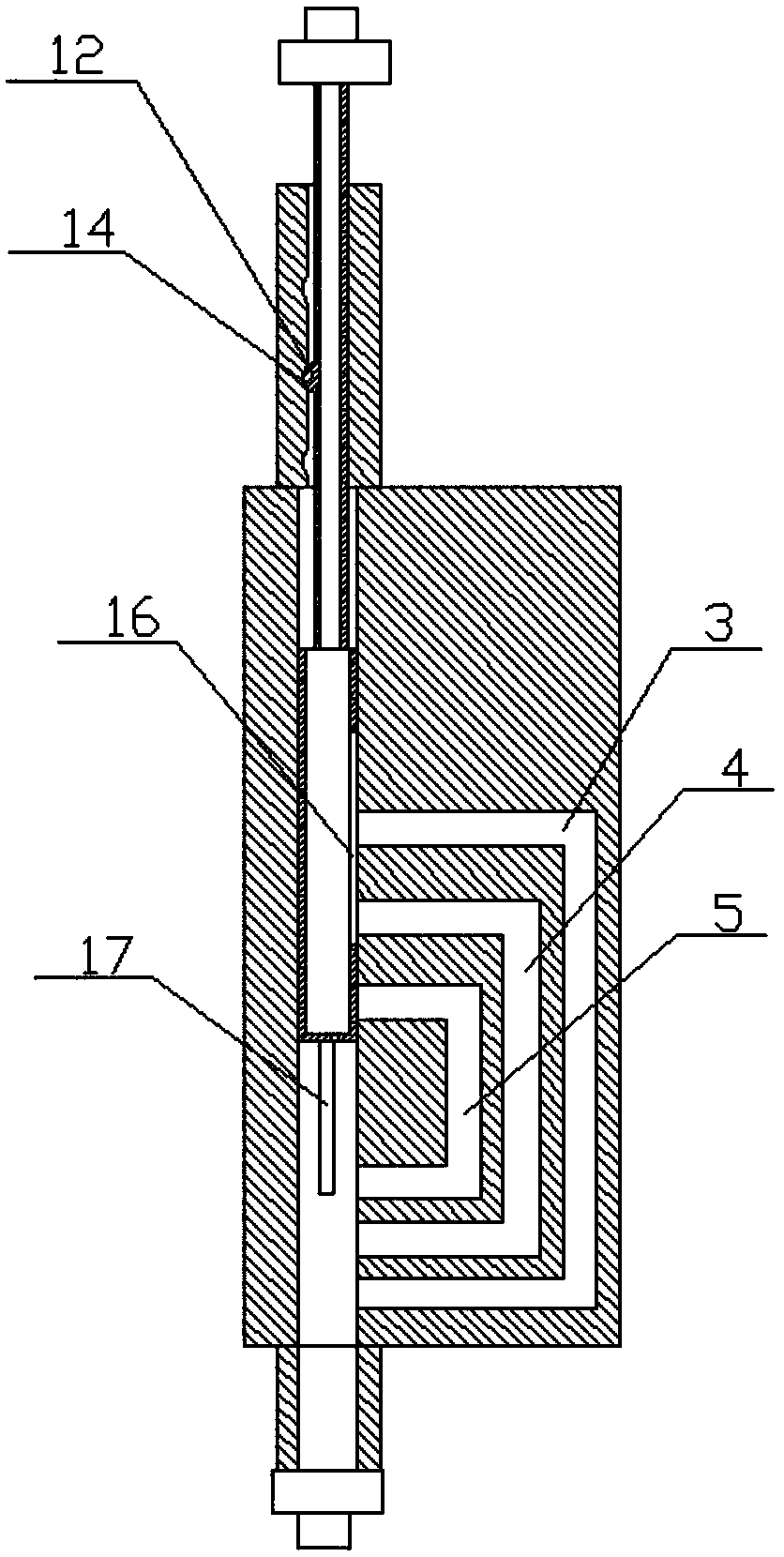
Multi-level flow control device applied to infusion pump
A technology of flow control device and infusion pump, which is applied in the direction of flow control, flow monitor, non-electric variable control, etc., can solve the problems that cannot meet the requirements of clinical use well, and achieve the realization of micro-accurate control and supply, control Simple and effective in meeting the requirements of clinical use
- Summary
- Abstract
- Description
- Claims
- Application Information
AI Technical Summary
Problems solved by technology
Method used
Image
Examples
Embodiment 1
[0023] Such as figure 1 As shown, a multi-stage flow control device applied to an infusion pump includes a valve body 1, the valve body 1 has a cylindrical valve cavity 2 that penetrates up and down, and the valve body 1 is also provided with side passages A3, Side channel B4 and side channel C5, the inlet ends of the side channel A3, side channel B4 and side channel C5 communicate with the middle end of the valve chamber 2 in turn from top to bottom, and the side channel C5, side channel B4 and side channel The outlet port of A3 communicates with the lower end of the valve chamber 2 respectively; the upper and lower ends of the valve body 1 are respectively provided with a protrusion A6 and a protrusion B7 communicating with the valve chamber 2, and the cavity cross-sectional area of the protrusion A6 is smaller than that of the valve body. The cross-sectional area of the cavity 2, the cavity of the protrusion A6 and the valve cavity 2 are connected with a valve stem, the...
Embodiment 2
[0030] Such as Figure 5As shown, a multi-stage flow control device applied to an infusion pump includes a valve body 1, the valve body 1 has a cylindrical valve cavity 2 that penetrates up and down, and the valve body 1 is also provided with side passages A3, Side channel B4 and side channel C5, the inlet ends of the side channel A3, side channel B4 and side channel C5 communicate with the middle end of the valve chamber 2 in turn from top to bottom, and the side channel C5, side channel B4 and side channel The outlet port of A3 communicates with the lower end of the valve chamber 2 respectively; the upper and lower ends of the valve body 1 are respectively provided with a protrusion A6 and a protrusion B7 communicating with the valve chamber 2, and the cavity cross-sectional area of the protrusion A6 is smaller than that of the valve body. The cross-sectional area of the cavity 2, the cavity of the protrusion A6 and the valve cavity 2 are connected with a valve stem, the...
PUM
 Abstract
Description
Claims
Application Information
 - R&D
- Intellectual Property
- Life Sciences
- Materials
- Tech Scout
- Unparalleled Data Quality
- Higher Quality Content
- 60% Fewer Hallucinations
Browse by: Latest US Patents, China's latest patents, Technical Efficacy Thesaurus, Application Domain, Technology Topic, Popular Technical Reports.
© 2025 PatSnap. All rights reserved.Legal|Privacy policy|Modern Slavery Act Transparency Statement|Sitemap|About US| Contact US: help@patsnap.com


