A wide-spectrum optical power beam splitter and power distribution method

A technology of power separation and broad-spectrum light, applied in instruments, optics, nonlinear optics, etc., can solve the problems of device loss, weak high-order electro-optical effects, and increased power consumption costs, achieving small size, wide working range, high Effects of process tolerances

Active Publication Date: 2020-09-01
PEKING UNIV
View PDF5 Cites 0 Cited by
  • Summary
  • Abstract
  • Description
  • Claims
  • Application Information

AI Technical Summary

Problems solved by technology

Thermal adjustment mainly applies the thermo-optic effect of silicon, and changes the refractive index by changing the temperature of the device structure. This method has a slow response speed and poor controllability.
Since silicon is a central inversion symmetric crystal, its first-order electro-optic coefficient is 0 and the high-order electro-optic effect is very weak, the electrical adjustment of the refractive index is mainly performed through the plasma dispersion effect of doped silicon, and the doping of free carriers will It leads to additional device loss, and using it as a splitting device greatly increases the cost of power consumption, so it is not suitable for optical power splitting structures

Method used


Image

  • A wide-spectrum optical power beam splitter and power distribution method
  • A wide-spectrum optical power beam splitter and power distribution method
  • A wide-spectrum optical power beam splitter and power distribution method

Examples


Embodiment Construction

[0022] In order to make the purpose, technical solutions and advantages of the embodiments of the present invention clearer, the technical solutions in the embodiments of the present invention will be clearly and completely described below in conjunction with the drawings in the embodiments of the present invention. Obviously, the described embodiments It is a part of embodiments of the present invention, but not all embodiments. Based on the embodiments of the present invention, all other embodiments obtained by persons of ordinary skill in the art without creative efforts fall within the protection scope of the present invention.

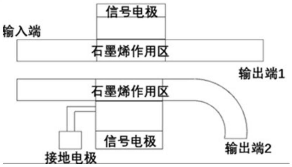
[0023] figure 1 A schematic structural diagram of a wide-spectrum optical power beam splitter provided for an embodiment of the present invention, as shown in figure 1 As shown, at least including: a first waveguide and a second waveguide, the first waveguide and the second waveguide have an interaction area, and the interaction area is a graphen...


PUM


Abstract

The invention provides a wide-spectrum optical power beam splitter and a power distribution method. The splitter includes a first waveguide and a second waveguide, an interaction zone is formed between the first waveguide and the second waveguide, and the interaction zone is a graphene waveguide action zone which is used for adjusting the optical conductivity of a graphene layer by adjusting the voltage of the graphene waveguide action zone to adjust output power. The wide-spectrum optical power beam splitter can change the ratio of the optical power of an output port, achieve on-chip reconstruction, and is small in size and wide in working range.

Description

technical field [0001] The invention relates to the technical field of optoelectronic integration, in particular to a wide-spectrum optical power beam splitter and a power distribution method. Background technique [0002] Optical power splitting devices are one of the important unit devices in integrated photonic systems. At present, the optical power splitting of the system-on-chip is mainly realized by the multimode interference coupler (Multimode Interference, MMI). Through the structural design of the multimode interference area, the self-image effect of the multimode waveguide can be used to achieve a smaller device size. A fixed-ratio optical power beam splitter is realized. The traditional multimode interference coupler realizes the power beam splitting function by etching the silicon waveguide in the multimode interference area to different degrees and changing the ratio of the optical power of the self-image point. However, once this type of structure is fabricat...

Claims


Application Information

Patent Timeline
Patent Type & Authority Patents(China)
IPC IPC(8): G02F1/01
CPCG02F1/0102G02F1/011
Inventor 舒浩文王兴军陶源盛金明
Owner PEKING UNIV
Why Eureka
Try Eureka