
Installation structure and installation method of concrete stress strain detection device

A stress-strain detection device technology, applied in the direction of measuring devices, connecting components, instruments, etc., can solve the problems of low installation and construction efficiency, taking up a lot of labor time, affecting installation accuracy, etc., and achieve high installation and construction efficiency, simple and labor-saving installation, The effect of high installation accuracy

Active Publication Date: 2018-07-17
NINGBO INST OF TECH ZHEJIANG UNIV ZHEJIANG +1
View PDF7 Cites 2 Cited by
  • Summary
  • Abstract
  • Description
  • Claims
  • Application Information

AI Technical Summary

Problems solved by technology

During the actual installation process of the above prior art detection device, due to the above-mentioned small installation block and the hard and heavy reasons, it is necessary to manually press the two small installation boards before installing the sensor for 30-40 minutes to stick them together. Its labor intensity is very high, it takes up too much manpower time, and its installation and construction efficiency is low; and there are phenomena such as the movement of the base position during the manual lifting process, which affects the installation accuracy, and the detection process is interrupted due to weak bonding

Method used


Image

  • Installation structure and installation method of concrete stress strain detection device
  • Installation structure and installation method of concrete stress strain detection device
  • Installation structure and installation method of concrete stress strain detection device

Examples


Embodiment Construction

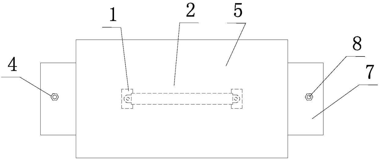
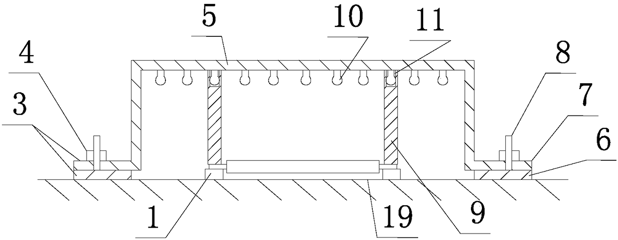
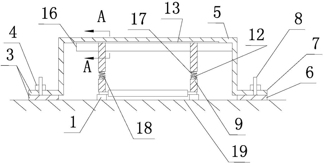
[0028] The specific embodiments of the present invention will be further described below in conjunction with the accompanying drawings. What needs to be declared here is that the descriptions of these embodiments are used to help understand the present invention, but are not intended to limit the present invention. In addition, the technical features and technical means involved in the various embodiments of the present invention described below may be combined with each other as long as they do not constitute a conflict with each other.

[0029] Such as figure 1 , figure 2 , image 3 , Figure 4 shown

[0030] The installation structure of the concrete stress-strain detection device of the present invention includes two small installation boards 1 glued to the concrete surface 19 of the stress-strain concentration area 2 and used for installing sensors. The stress and strain concentration area 2 can also be called a detection area. The small mounting board 1 can also b...


PUM


Abstract

The invention discloses an installation structure and an installation method of a concrete stress strain detection device. The installation structure of the concrete stress strain detection device comprises two small installation plates adhered to a concrete surface of a stress strain concentration region and used for installing sensors, and two large installation plates adhered to concrete surfaces of two sides of the two small installation plates, wherein a sensor protection cover is arranged on the two large installation plates and is detachably connected with the two large installation plates; pressing devices, i.e. two pressing pillars aiming at the two small installation plates are detachably arranged in the sensor protection cover; and the two pressing pillars align at the two smallinstallation plates, and meanwhile, the sensor protection cover is screwed down through locking nuts, so that the pressing pillars apply pressure on the two small installation plates. The installation structure and the installation method endow the sensor protection cover with novel functions and actions, no manual pressing is needed, and the installation can be carried out simply and conveniently in a labor-saving way, and the installation construction efficiency is high.

Description

technical field [0001] The invention relates to the technical field of civil engineering structure detection, in particular to an installation structure and an installation method of a concrete stress and strain detection device. Background technique [0002] Civil engineering structures such as bridges, tunnels and wharves will be damaged to a certain extent with the increase of service life and changes in geological conditions. Generally speaking, when this phenomenon is relatively light, it will not affect civil engineering structures and vehicles on them and For the safety of human life, it is not necessary to deal with it first, but a detection device such as a strain sensor electrically connected to an information processing unit can be installed in the stress and strain concentration area to monitor the stress and strain development status at all times. In order to prevent structural damage caused by perforated installation, the current detection device in the prior a...

Claims


Application Information

Patent Timeline
IPC IPC(8): F16B11/00G01D21/02
CPCF16B11/006G01D21/02
Inventor 毛江鸿张军许斌锋金伟良罗伟锦王华俊樊玮洁俞凯奇
Owner NINGBO INST OF TECH ZHEJIANG UNIV ZHEJIANG
Learn More