
Feeding equipment for coil spring machining

A technology for feeding equipment and coil springs, which is applied in the field of feeding equipment for coil spring processing, can solve the problems of poor device stability, large pulling force, unstable feeding mechanism, etc., and achieve the effect of high stability and small pulling force.

Inactive Publication Date: 2018-07-17
黄巧珍
View PDF1 Cites 0 Cited by
  • Summary
  • Abstract
  • Description
  • Claims
  • Application Information

AI Technical Summary

Problems solved by technology

[0002] Chinese patent CN105329627A discloses a helical spring feeding mechanism. This file sets a feeding tray, and the steel wire is placed on the feeding tray, and the whole steel wire is driven to rotate by the feeding tray. Larger size leads to heavier weight, so if the coil spring machine is used to directly pull the steel wire without setting up a motor to drive the feeding disc to rotate, a larger pulling force is required, which requires high power of the device and a fast speed during the pulling process, so The entire feeding tray will rotate rapidly, and under this rapid rotation, it is very easy to cause the feeding mechanism to be unstable and topple over, and the stability of the device is poor

Method used


Image

  • Feeding equipment for coil spring machining
  • Feeding equipment for coil spring machining
  • Feeding equipment for coil spring machining

Examples


Embodiment Construction

[0019] In order to enable those skilled in the art to better understand the solutions of the present invention, the technical solutions in the embodiments of the present invention will be clearly and completely described below in conjunction with the drawings in the embodiments of the present invention.

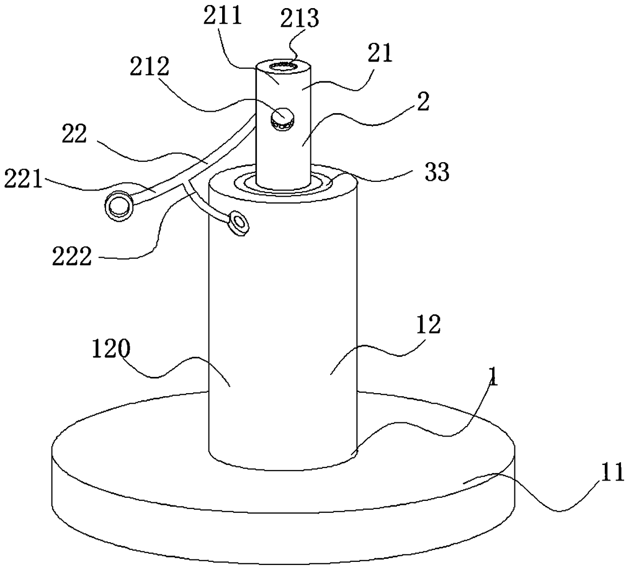
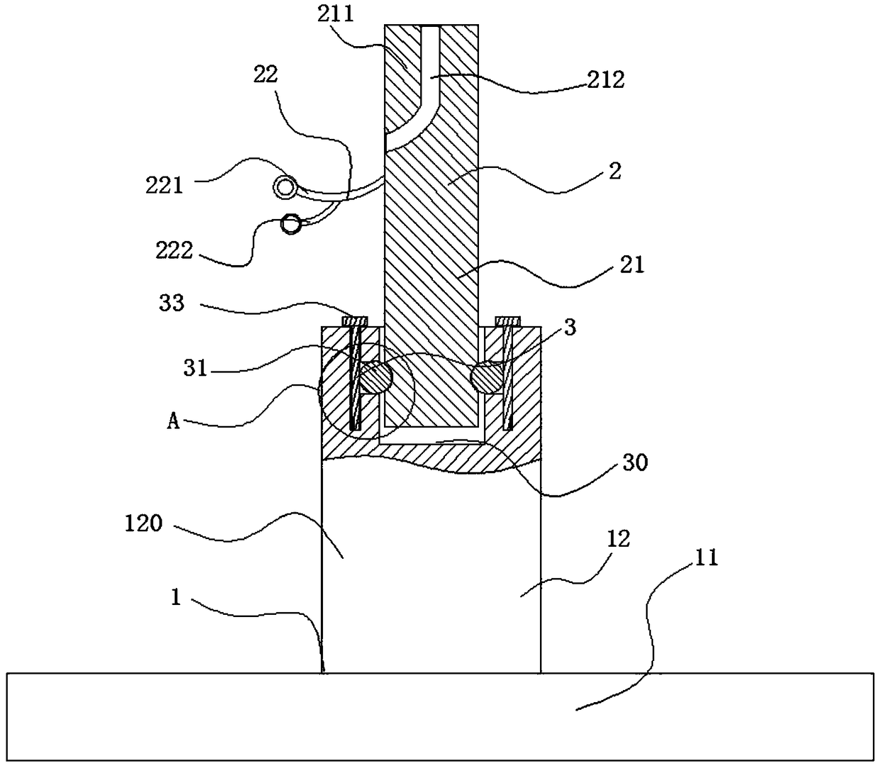
[0020] Such as Figure 1-4 As shown, a feeding device for coil spring processing includes a discharging mechanism 1 and a rotating mechanism 2, wherein the discharging mechanism 1 includes a base 11 and a stopper 12, and the base 11 is a disc Shaped metal block, the limiting part 12 includes a limiting part 120, the limiting part 120 is a metal cylinder, the limiting part 12 is vertically fixed on the base 11; the coiled steel wire is directly sleeved on the On the limiting member 120 ; the rotating mechanism 2 is arranged on the limiting member 120 and can rotate on the limiting member 120 .

[0021] Further, the rotating mechanism 2 includes a rotating part 21 and a restri...


PUM


Abstract

The invention discloses feeding equipment for coil spring machining. The feeding equipment comprises a discharging mechanism and a rotating mechanism movably connected with the discharging mechanism.The discharging mechanism comprises a base and a limiting component used for primarily locating a spring raw material. The rotating mechanism comprises a rotating component used for secondarily locating the spring raw material and a limitation component cooperating with the rotating component, and the rotating component cooperates with the limiting component. According to the feeding equipment, when a steel wire is pulled, the limiting component containing the steel wire does not move, the rotating component rotates, and therefore a whole steel wire ring does not move, and only the steel wireis pulled; and stability generated when the steel wire is pulled in the manner is high, and the pulling force in the steel wire pulling process is small.

Description

technical field [0001] The invention belongs to the technical field of coil spring production, and in particular relates to a material feeding device for coil spring processing. Background technique [0002] Chinese patent CN105329627A discloses a helical spring feeding mechanism. This file sets a feeding tray, and the steel wire is placed on the feeding tray, and the whole steel wire is driven to rotate by the feeding tray. Larger size leads to heavier weight, so if the coil spring machine is used to directly pull the steel wire without setting up a motor to drive the feeding disc to rotate, a larger pulling force is required, which requires high power of the device and a fast speed during the pulling process, so The entire feeding tray will rotate rapidly, and under this rapid rotation, it is very easy to cause the feeding mechanism to be unstable and topple over, and the stability of the device is poor. Contents of the invention [0003] In order to overcome the defici...

Claims


Application Information

Patent Timeline
Patent Type & Authority Applications(China)
IPC IPC(8): B21F23/00
CPCB21F23/00
Inventor 黄巧珍
Owner 黄巧珍
Learn More