
Transfer needle for a knitting machine

A technology of transfer needles and knitting machines, which can be used in knitting, textiles and papermaking, and can solve the problems of high-tech costs

Active Publication Date: 2006-02-22
KARL MAYER STOLL R&D GMBH
View PDF2 Cites 0 Cited by
  • Summary
  • Abstract
  • Description
  • Claims
  • Application Information

AI Technical Summary

Problems solved by technology

The disadvantage is that the box spring continues to protrude from the needle neck and requires additional play in the needle path
The introduction of this gap requires high technical outlay and corresponding costs

Method used


Image

  • Transfer needle for a knitting machine
  • Transfer needle for a knitting machine
  • Transfer needle for a knitting machine

Examples


Embodiment Construction

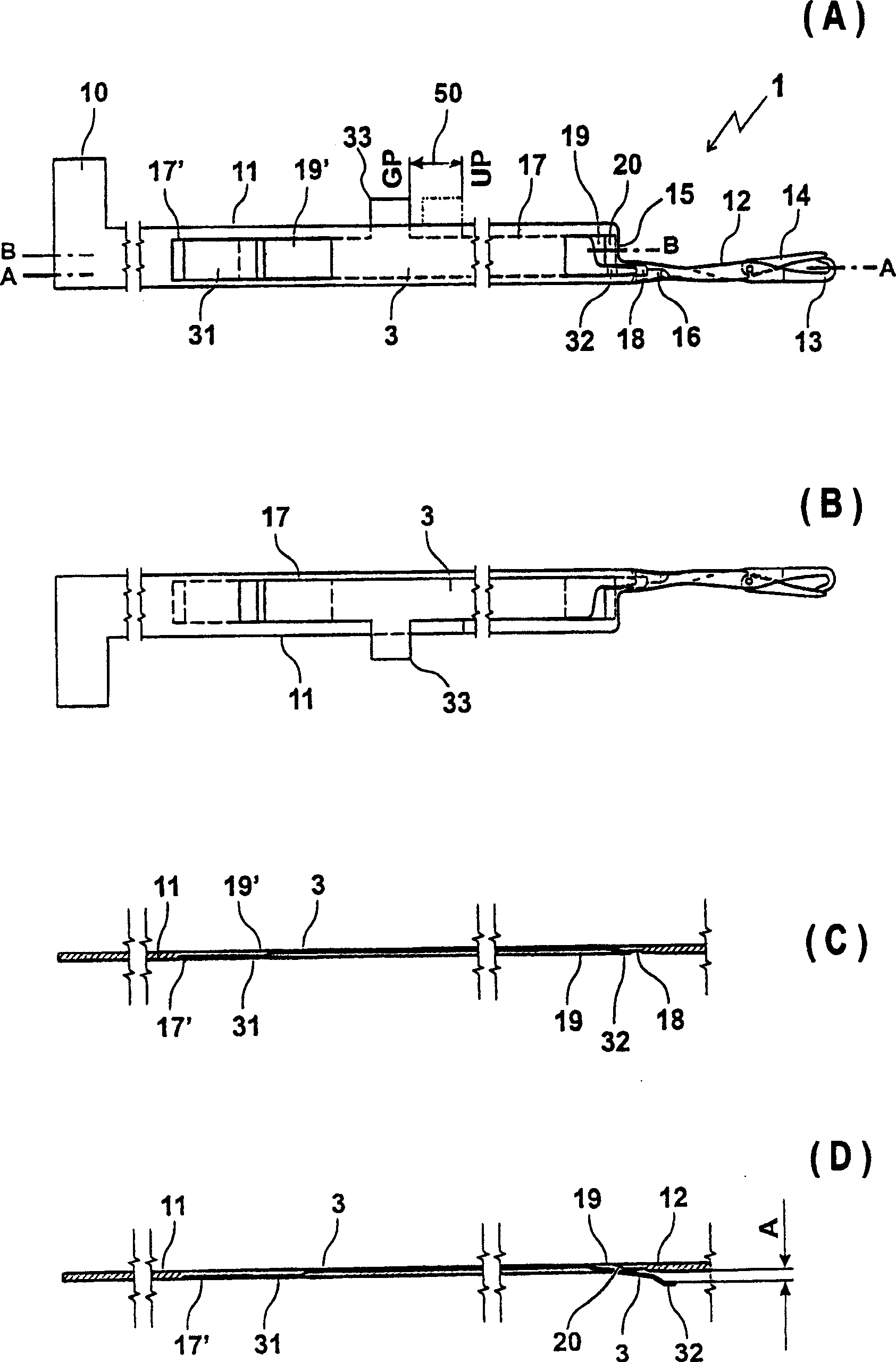
[0019] Depend on figure 1 a) It can be seen that the transfer needle 1 has a transfer spring 3 guided in the needle body 11, which is movable in the longitudinal direction of the needle body 11 from its base position GP to its transfer position in one direction of the double arrow 50. The circle position UP can be returned to its base position GP in the other direction.

[0020] The needle neck 12 , needle hook 13 , tongue 14 , needle belly 15 and recess 16 of the transfer needle 1 largely correspond to transfer needles with known hard box-type transfer springs.

[0021] The needle body 11 is provided with a groove 17 along the longitudinal side, and the depth and height of the groove are designed so that the groove forms a guiding device and a sliding surface for the transfer spring 3 .

[0022] At the end of the needle body 11 formed by the needle belly 15 , the groove 17 has a perforation 19 over its entire height, which ends with a bevel 20 towards the needle belly 15 . ...


PUM


Abstract

A knitting machine transfer needle 1 has a transfer spring 3 which is supported movably from an initial position to a transfer position and, again, to the initial position. To form a space A between the transfer needle 1 and the transfer spring 3, a means 20 for turning the transfer spring 3 when moving from the initial position to the transfer position is provided. The invention is intended to provide a transfer needle having a transfer spring capable of acting in ordinary needle grooves and ensuring sure transfer of stitch.

Description

technical field [0001] The invention relates to a transfer needle for a knitting machine, wherein the transfer needle has a transfer spring. Background technique [0002] A transfer needle with a stiff spring is known, for example, from DE 3145708 A1. [0003] For all stitch transfer methods from needle to needle, a transfer needle is required, in which there is a free space at the transfer point of the stitch, through which the hook of the transfer needle is guided to transfer the stitch. [0004] Corresponding to the prior art, transfer springs are used to provide this free space. Known transfer springs are fixedly connected to the longitudinal sides of the needle in the region of the needle belly. The free space between the transfer spring and the transfer needle neck is determined by the curved shape of the transfer spring. [0005] Two types of coil transfer springs are known: tension springs and box springs. [0006] In the case of a pulling spring, as is shown for...

Claims


Application Information

Patent Timeline
Patent Type & Authority Applications(China)
IPC IPC(8): D04B35/02
CPCD04B35/02D04B35/04
Inventor H・施莫德
Owner KARL MAYER STOLL R&D GMBH
Learn More