A Frequency Selective Surface Type Curved Medium and Cassegrain Antenna System

A frequency selection, surface-type technology, applied to antennas, waveguide horns, electrical components, etc., can solve the problems of no periodic characteristics, polarization instability, frequency drift, etc., to achieve convenient fixing, reduce processing difficulty, and work frequency The effect of bandwidth

Active Publication Date: 2020-10-30
ANHUI SUN CREATE ELECTRONICS
View PDF7 Cites 0 Cited by
  • Summary
  • Abstract
  • Description
  • Claims
  • Application Information

AI Technical Summary

Problems solved by technology

The FSS of the curved surface structure does not show strict periodic characteristics similar to the FSS of the infinite planar structure. Therefore, when the electromagnetic wave is incident, it will produce characteristics such as frequency drift and polarization instability, which makes the analysis of the problem relatively complicated.

Method used


Image

  • A Frequency Selective Surface Type Curved Medium and Cassegrain Antenna System
  • A Frequency Selective Surface Type Curved Medium and Cassegrain Antenna System
  • A Frequency Selective Surface Type Curved Medium and Cassegrain Antenna System

Examples


Embodiment 1

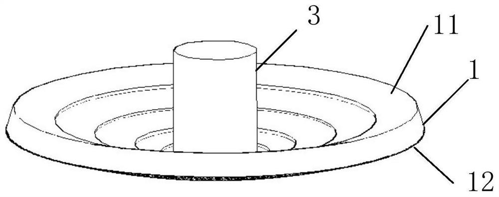
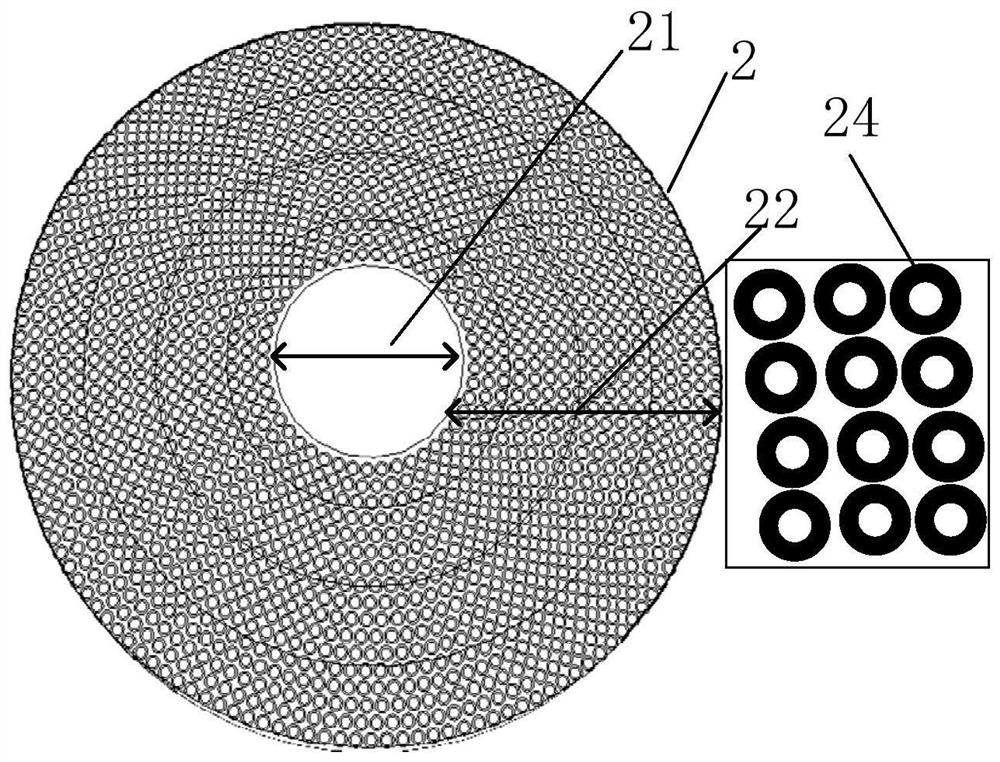
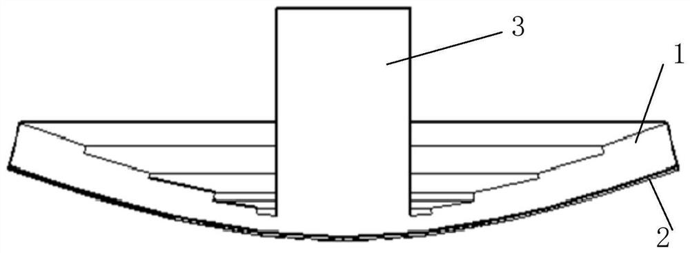
[0035] like Figure 1-3 As shown, a frequency-selective surface-type curved medium includes a dielectric substrate 1. The dielectric substrate 1 is made of a dielectric material with good wave-transmitting performance and low dielectric loss. In this embodiment, the material of the dielectric substrate 1 is polytetrafluoroethylene , The dielectric constant is 2.1. The upper surface 12 of the medium base 1 is a pot-shaped curved surface, and the lower surface 11 is a shape formed by cutting toward the upper surface 12 of the medium base 1 on the basis of the same shape of the upper surface 12, so that the upper surface 12 of the medium base 1 reaches the lower surface The vertical distance of 11 decreases successively from the outer edge to the center of the dielectric substrate 1; in this embodiment, the outer edge to the center of the lower surface 11 of the dielectric substrate 1 is stepped, that is, the thickness of the dielectric substrate 1 is different according to the e...

Embodiment 2

[0042] See attached Figure 4 , the Cassegrain antenna system including the frequency-selective surface-type curved medium described in Embodiment 1 further includes a main reflector 7 , a feed horn 4 , a fixing bracket 5 , and a feed sleeve 6 . The frequency-selective surface-type curved medium is fixed to the outer surface of the feed horn 4 through the fixing bracket 5, and the metal layer 2 in the frequency-selective surface-type curved medium is used as a secondary reflector, which is opposite to the main reflector 7. The other end of the feed horn 4 is directly fixed to the center of the main reflection surface 7 through the feed sleeve 6 , and the internal feeder of the feed horn 4 is directly connected to the back-end transceiver system. Due to the unique characteristics of the present invention, not only the Ka-band and W-band common aperture requirements are realized, but also the Ka-band and W-band can irradiate different main surface working areas, and the purpose ...


PUM


Abstract

The invention discloses a frequency selection surface type curved surface dielectric and a cassegrain antenna system. The curved surface dielectric comprises a dielectric substrate; the upper surfaceof the dielectric substrate is a pot cover-shaped curved surface, while the lower surface adopts a shape which is cut towards the upper surface of the dielectric substrate on the basis of the same shape of the upper surface, so that the perpendicular distance from the upper surface to the lower surface of the dielectric substrate is gradually reduced from the outer edge to the center of the dielectric substrate; the upper surface of the dielectric substrate is attached with a metal layer of the set thickness; total reflection of energy at the required waveband is realized in the middle regionof the pot cover-shaped metal layer; and gap units of the same sizes are arranged on the metal layer of a peripheral region in an annular array form, so that transmission of the energy at the requiredwaveband is realized. The curved surface dielectric has the advantages as follows: by adjusting the thicknesses from the outer edge to the center of the dielectric substrate, changes of the dimensions of the gaps in the metal layer from the outer edge to the center is not needed even if the projection angle is changed, thereby greatly lowering the processing difficulty.

Description

technical field [0001] The invention relates to the technical field of antenna reflection surfaces, in particular to a frequency-selective surface-type curved surface medium and a Cassegrain antenna system. Background technique [0002] With the advancement of domestic millimeter-wave technology, millimeter-wave cloud radar technology has also developed rapidly. Due to their inherent defects, single-band cloud radars can no longer meet the needs of the current system. The development of dual-band or multi-band Cloud radar is imperative. Early dual-wavelength detection used dual radars, that is, two radars with different bands were turned on at the same time to detect the same target. The biggest problem with this method is that it is difficult to ensure that the two radars detect the same target, and the amount of equipment is large, and the operation and maintenance requirements are high. Common-aperture antenna radar is an effective method to solve the above problems. C...

Claims


Application Information

Patent Timeline
Patent Type & Authority Patents(China)
IPC IPC(8): H01Q15/00H01Q19/19H01Q13/02
CPCH01Q13/02H01Q15/0013H01Q19/19
Inventor 李运志胡卫东孙浩金秀梅
Owner ANHUI SUN CREATE ELECTRONICS
Why Eureka
Try Eureka