Screw-lifting-type building steel bar equal-distance automatic cutting device

An automatic cutting device and a technology for building steel bars, which are applied in the field of cutting devices, can solve the problems of increasing the user's risk, reducing the user's work efficiency, and causing injury to the user, so as to reduce the risk of accidental injury to the operator, improve safety, Practical effect

Inactive Publication Date: 2018-07-13
HENAN GAOSHENG ENTERPRISE MANAGEMENT CONSULTING CO LTD
View PDF7 Cites 4 Cited by
  • Summary
  • Abstract
  • Description
  • Claims
  • Application Information

AI Technical Summary

Problems solved by technology

[0003] In building construction, steel bar is used as the skeleton of concrete to form reinforced concrete, which has become the main material with a wide range of uses and large quantities in building structures. Before pouring concrete, the steel bar must be made into a skeleton of a certain size and form and incorporated into the formwork to make a steel bar skeleton. , it is necessary to strengthen, stretch, straighten, cut, bend, connect and process the steel bars before they can be bundled and formed. In the process of steel bar processing, the cutting of steel bars is also a very important process. The existing steel bar cutting machines for building construction are large Most of them are manually clamped for cutting, which is very dangerous and can easily cause injury to the user. It not only reduces the work efficiency of the user, but also increases the danger of the user when using it.

Method used


Image

  • Screw-lifting-type building steel bar equal-distance automatic cutting device
  • Screw-lifting-type building steel bar equal-distance automatic cutting device
  • Screw-lifting-type building steel bar equal-distance automatic cutting device

Examples


Embodiment Construction

[0019] The technical solution of this patent will be further described in detail below in conjunction with specific embodiments.

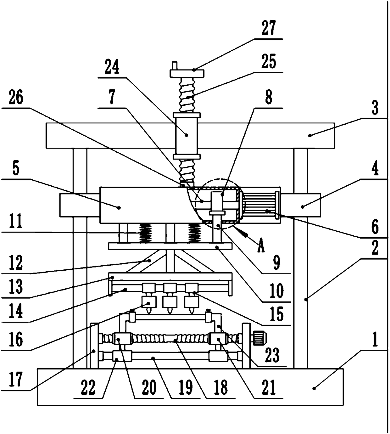
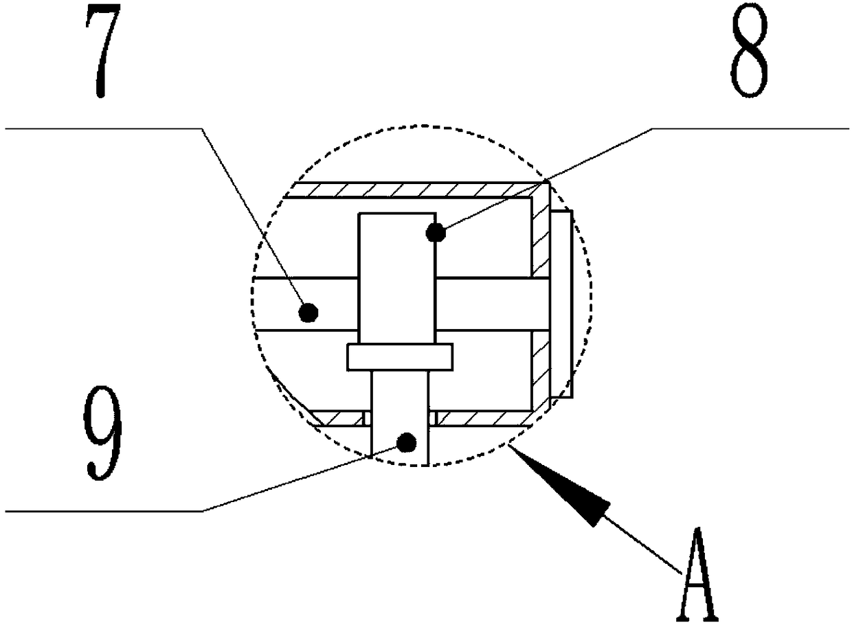
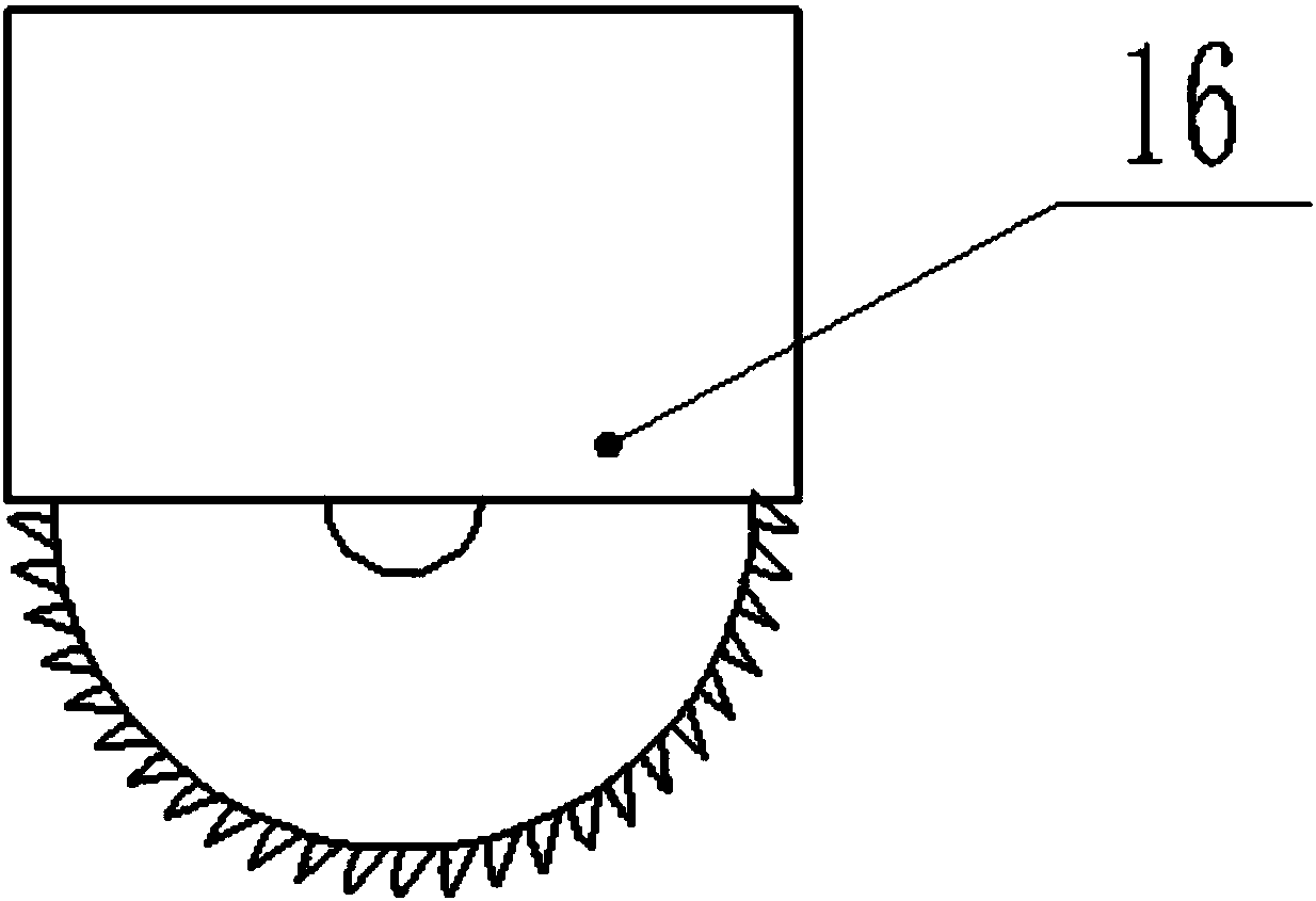
[0020] see Figure 1-3 , a screw lift type construction steel bar isometric automatic cutting device, comprising a base 1, a device box 5, a cutting machine 16, a ball screw 18, a left screw sleeve 20 and a right screw sleeve 21, the upper surface of the base 1 has two left and right sides. The side is symmetrically provided with supporting sliding columns 2, and the supporting sliding columns 2 and the base 1 are connected by welding. The guide installation ears 4 are slidingly installed, and the device box 5 is fixedly connected with the guide installation ears 4 on the left and right sides by screws. The output shaft of the drive motor 6 is horizontal to the left and the output shaft of the drive motor 6 is fixedly connected with the connecting shaft 7 through a shaft coupling. The interference fit on the connecting shaft 7 is equipped with a c...


PUM


Abstract

The invention discloses a screw-lifting-type building steel bar equal-distance automatic cutting device which comprises a base, a device box, cutting machines, a ball screw, a left screw sleeve and aright screw sleeve, wherein the device box is fixedly connected between guiding-mounting lugs positioned on the left and right sides through screws; a plurality of groups of fixing rod sleeves are slidably mounted on a sliding rod; the cutting machines are arranged on the lower sides of the fixing rod sleeves; and fixing rods are welded with the upper sides of both the left screw sleeve and the right screw sleeve. The screw-lifting-type building steel bar equal-distance automatic cutting device can meets the requirements of steel bars of different lengths and is convenient to adjust; the university of the screw-lifting-type building steel bar equal-distance automatic cutting device is high; furthermore, the spaces among the cutting machines can be randomly adjusted in the cutting course and a steel bar can be cut into required short steel bars of various lengths; besides, the steel bar need not be manually held in the cutting course, thereby effectively reducing the risk that operatingpersonnel are accidentally injured by the cutting machines and greatly improving the operating safety; and the operation is simple and the practicability is high.

Description

technical field [0001] The invention relates to a cutting device, in particular to a screw rod lifting type automatic cutting device for equidistant construction steel bars. Background technique [0002] Steel bar refers to steel for reinforced concrete and prestressed reinforced concrete. The straight or coiled steel used for reinforcement is divided into two types: smooth round steel bar and deformed steel bar, and the delivery state is straight bar and coiled round. [0003] In building construction, steel bars are used as the skeleton of concrete to form reinforced concrete, which has become the main material with a wide range of uses and large quantities in building structures. Before pouring concrete, the steel bars must be made into a skeleton of a certain size and form and incorporated into the formwork to make a steel bar skeleton. , it is necessary to strengthen, stretch, straighten, cut, bend, connect and other processes on the steel bars before they can be bundl...

Claims


Application Information

Patent Timeline
Patent Type & Authority Applications(China)
IPC IPC(8): B21F11/00
CPCB21F11/00
Inventor 李盼君
Owner HENAN GAOSHENG ENTERPRISE MANAGEMENT CONSULTING CO LTD
Why Eureka
Try Eureka