
Control method of safety valve

A control method and valve technology, applied in the valve operation/release device, sliding valve, valve details, etc., can solve the problems of lack of conditions, inability to meet equipment use conditions, etc., and achieve the effect of energy saving

Inactive Publication Date: 2018-07-10
CHENGDU JINHUI TECH
View PDF0 Cites 5 Cited by
  • Summary
  • Abstract
  • Description
  • Claims
  • Application Information

AI Technical Summary

Problems solved by technology

These safety shut-off valves can meet 70% of the market demand, but there are still some well stations that cannot meet the conditions of use of these equipment due to lack of conditions

Method used


Image

  • Control method of safety valve
  • Control method of safety valve

Examples


Embodiment 1

[0031] As a preferred embodiment of the present invention, this embodiment discloses a method for controlling a safety valve, and this embodiment includes:

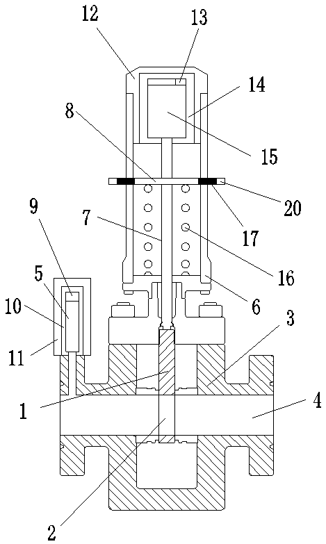
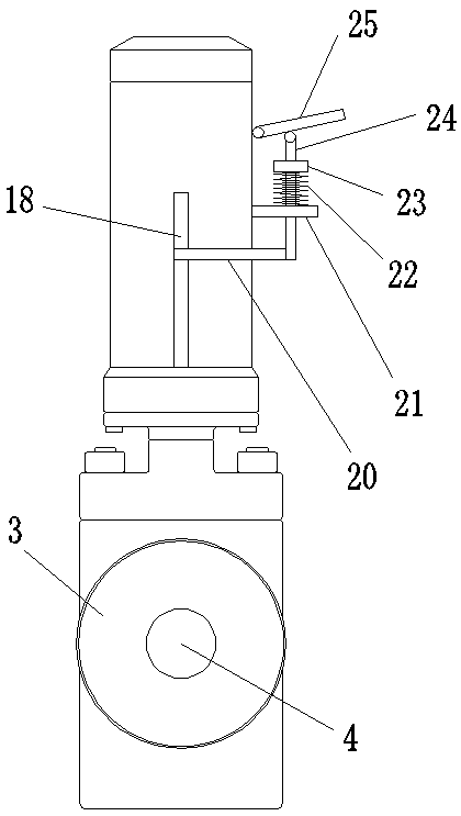
[0032] A method for controlling a safety valve, comprising: a pressure sensor 5 detects the pressure of a pressure pipeline 4 in real time, and when the pressure sensor 5 detects that the pressure of the pressure pipeline 4 is too high, the wireless communication device 1 9 transmits a signal to the wireless communication device 2 13; Cylinder 15 starts after receiving the information, pushes the movable plate 8 downward, and the valve stem 7 under the movable plate 8 drives the gate 1 to move downward to close the valve; when the cylinder 5 fails to close the valve due to failure, The valve can be closed by an emergency shut-off device; the pressure pipeline 4 is faulty removed, and when the valve needs to be opened, the cylinder 5 releases the thrust, and the gate plate 1 moves upward under the elastic force of the sprin...

Embodiment 2

[0043] As a preferred embodiment of the present invention, this embodiment discloses a method for controlling a safety valve, and this embodiment includes:

[0044] A method for controlling a safety valve, comprising: a pressure sensor 5 detects the pressure of a pressure pipeline 4 in real time, and when the pressure sensor 5 detects that the pressure of the pressure pipeline 4 is too high, the wireless communication device 1 9 transmits a signal to the wireless communication device 2 13; Cylinder 15 starts after receiving the information, pushes the movable plate 8 downward, and the valve stem 7 under the movable plate 8 drives the gate 1 to move downward to close the valve; when the cylinder 5 fails to close the valve due to failure, The valve can be closed by an emergency shut-off device; the pressure pipeline 4 is faulty removed, and when the valve needs to be opened, the cylinder 5 releases the thrust, and the gate plate 1 moves upward under the elastic force of the sprin...


PUM


Abstract

The invention relates to the technical field of valves, in particular to a control method of a safety valve. The pressure of a pressure pipeline is detected through a pressure sensor; and when the pressure of the pressure pipeline is excessive, a wireless communication device I transmits a signal to a wireless communication device II, an air cylinder downwards pushes a movable plate, and a valve rod under the movable plate drives a gate to move downwards so as to close a valve and cut off medium conveyance. When the valve cannot be closed due to fault occurred on the air cylinder, the valve isclosed through an emergency shutoff device. A control method of the emergency shutoff device is characterized in that the end part of a handle is pressed, the handle downwards pushes a vertical rod,the vertical rod drives a connecting rod to move downwards, and the connecting rod drives the movable plate to move downwards, so that the valve is closed. When the pressure pipeline returns to normal, and the valve needs to be opened, the pressing on the handle is released, the vertical rod returns back in position under an elastic action of a spring II, the movable plate returns back in positionunder an elastic action of a spring I, and the gate is lifted upwards, so that the valve is opened.

Description

technical field [0001] The invention relates to the technical field of valves, in particular to a control method for a safety valve. Background technique [0002] High-pressure pipelines and containers in the oil and gas industry are at risk of rupture due to long-term use, medium corrosion and erosion. It may pose a serious threat to personnel safety and environmental pollution. With the country's increasing emphasis on safety and environmental protection, oil and natural gas production units have introduced some new policies to ensure safety and environmental protection. All valve manufacturers have begun to study the technology of safety shut-off valves. Now there are standard safety valves on the market. Conventional control methods include electric, pneumatic, hydraulic and pipeline pressure self-driven. The main purpose of safety shut-off valves When the pressure fluctuates greatly, it can cut off the transmission of pipeline medium by itself, so as to achieve the pur...

Claims


Application Information

Patent Timeline
IPC IPC(8): F16K3/02F16K31/02F16K31/14
CPCF16K3/0254F16K31/02F16K31/14
Inventor 张一帆
Owner CHENGDU JINHUI TECH
Learn More