
Reinforced concrete shear wall with anchor steel shearing-resistance reinforcing function and frame of reinforced concrete shear wall

A reinforced concrete and shear wall technology, applied in the direction of walls, building components, buildings, etc., can solve the problems of peeling damage, end anchor damage, inability to strengthen the restraint of concrete components, etc., to improve compression reinforcement, avoid stress concentration, The effect of not reducing the ductility

Inactive Publication Date: 2018-07-10
TONGJI UNIV
View PDF2 Cites 5 Cited by
  • Summary
  • Abstract
  • Description
  • Claims
  • Application Information

AI Technical Summary

Problems solved by technology

[0002] The existing shear strengthening methods for reinforced concrete coupling beams and frames mainly include pasting U-shaped steel hoops or fiber reinforced composite (FRP) wrapping methods. The former method often causes end anchoring due to the interface peeling at the ends of the steel hoops. damage, the latter method is difficult to achieve closed wrapping when there is a floor slab, and cannot form effective restraint reinforcement on concrete members, and peeling failure similar to the former method occurs

Method used


Image

  • Reinforced concrete shear wall with anchor steel shearing-resistance reinforcing function and frame of reinforced concrete shear wall
  • Reinforced concrete shear wall with anchor steel shearing-resistance reinforcing function and frame of reinforced concrete shear wall
  • Reinforced concrete shear wall with anchor steel shearing-resistance reinforcing function and frame of reinforced concrete shear wall

Examples


Embodiment Construction

[0020] The present invention will be described in detail below in conjunction with the accompanying drawings and specific embodiments. This embodiment is carried out on the premise of the technical solution of the present invention, and detailed implementation and specific operation process are given, but the protection scope of the present invention is not limited to the following embodiments.

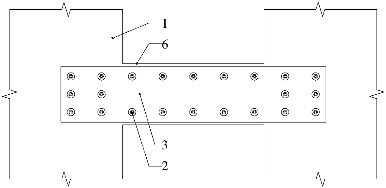
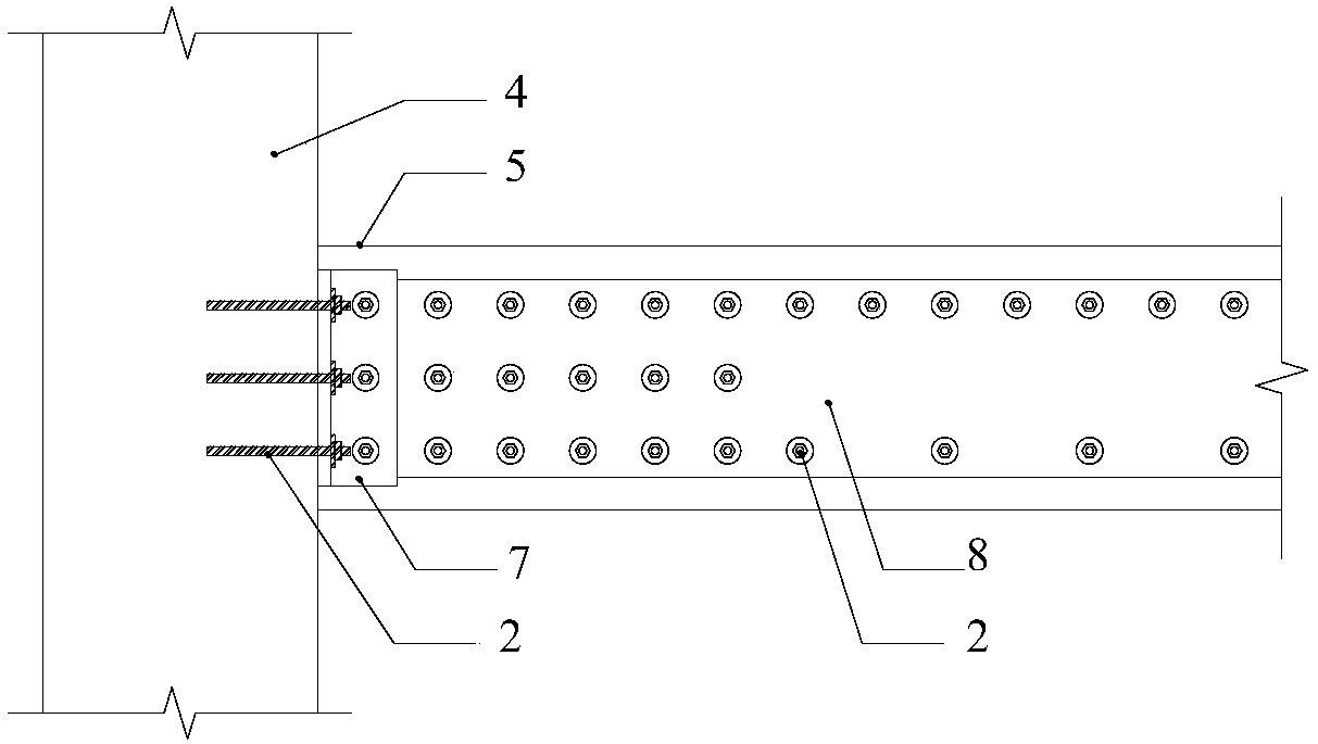
[0021] This application can be widely used in the reinforcement and transformation of the shear wall 1 and frame structure and its post-disaster repairs such as earthquakes and fires. The steel plate 24 on the side of the beam and the shear wall 1 and its connecting beam 6, or the joint work of frame beams and columns, so that the excellent shear performance of the beam side steel plate 24 in its own plane and its synergy with the reinforced concrete structure are used to realize the shear resistance of the reinforced concrete connecting beam 6 or frame beam 5 reinforcement.

[0022]...


PUM


Abstract

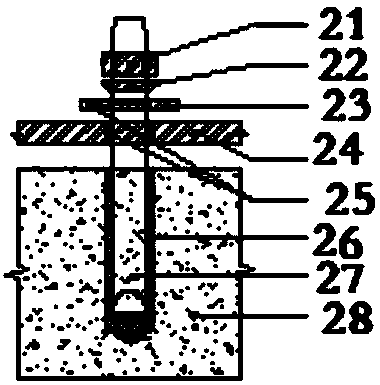
The invention relates to a reinforced concrete shear wall with an anchor steel shearing-resistance reinforcing function and a frame of the reinforced concrete shear wall. The reinforced concrete shearwall with the anchor steel shearing-resistance reinforcing function and the frame of the reinforced concrete shear wall comprise a shear wall body and a frame body and further comprise bar-planting type rear anchoring connecting structures, first side beam steel plates and second side beam steel plates; the frame body comprises a frame column and a frame beam which are arranged perpendicularly toeach other; the frame column is connected with the frame beam through beam-column connecting angle steel; the first side beam steel plates are connected to the shear wall body through the multiple bar-planting type rear anchoring connecting structures; and after the second side beam steel plates are connected to the frame beam through the multiple bar-planting type rear anchoring connecting structures, the side edges of the second side beam steel plates are connected to the frame column. Compared with the prior art, according to the reinforced concrete shear wall with the anchor steel shearing-resistance reinforcing function and the frame of the reinforced concrete shear wall, shearing force between the steel plates and concrete components are transmitted by adopting the bar-planting typerear anchoring connecting structures, thus the internal force of the steel plates can be directly transmitted into the concrete components, in addition, anchoring bolts have the certain shear deformation ability, internal force redistribution of the shearing force between all the anchoring bolts can be achieved, and the stress concentration phenomenon is avoided.

Description

technical field [0001] The invention relates to a shear wall and a frame, in particular to a reinforced concrete shear wall with anchor steel shear reinforcement and a frame thereof. Background technique [0002] The existing shear strengthening methods for reinforced concrete coupling beams and frames mainly include pasting U-shaped steel hoops or fiber reinforced composite (FRP) wrapping methods. The former method often causes end anchoring due to the interface peeling at the ends of the steel hoops. The latter method is difficult to achieve closed wrapping when there is a floor slab, and cannot form effective restraint reinforcement on concrete members, and peeling failure similar to the former method occurs. Contents of the invention [0003] The object of the present invention is to provide a reinforced concrete shear wall with anchor steel shear reinforcement and its frame in order to overcome the above-mentioned defects in the prior art. [0004] The purpose of the...

Claims


Application Information

Patent Timeline
Patent Type & Authority Applications(China)
IPC IPC(8): E04B2/56
CPCE04B2/56
Inventor 白洋张晓亮李凌志魏锴吴薇陈宇
Owner TONGJI UNIV
Learn More