
Simple pedal type back pounding massage machine

A pedal-type, simple technology, applied in vibration massage, massage auxiliary products, physiotherapy and other directions, can solve the problems of low reliability, single working mode, and high use limitations, and achieves improved use reliability and diverse working modes. , the use of limited effects

Inactive Publication Date: 2018-07-10
何洋洋
View PDF7 Cites 2 Cited by
  • Summary
  • Abstract
  • Description
  • Claims
  • Application Information

AI Technical Summary

Problems solved by technology

[0002] As we all know, the back-beating massage machine is a device that beats the appropriate parts of the back for people who are overtired and uncomfortable, so as to massage the user appropriately, thereby relieving the fatigue of the user, and is widely used in daily life. Existing back massager comprises connecting rod, two groups of springs, hammer body, two groups of massage balls and two groups of supports, the top of the connecting rod is connected with the bottom of the hammer body, and the two groups of supports are respectively fixed on the On the front side wall and the rear side wall of the hammer body, the two groups of massage balls are respectively installed on the left ends of the two groups of brackets, and the two groups of springs are respectively installed in the two groups of massage balls; At this time, the user holds the connecting rod and moves to a suitable position on the back to beat, so as to drive two groups of massage balls to beat and massage the user's back; It has high limitations and low practicability; moreover, its single working mode cannot provide users with proper exercise, and the physical therapy effect is poor, resulting in low reliability in use

Method used


Image

  • Simple pedal type back pounding massage machine
  • Simple pedal type back pounding massage machine
  • Simple pedal type back pounding massage machine

Examples


Embodiment Construction

[0014] The specific implementation manners of the present invention will be further described in detail below in conjunction with the accompanying drawings and embodiments. The following examples are used to illustrate the present invention, but are not intended to limit the scope of the present invention.

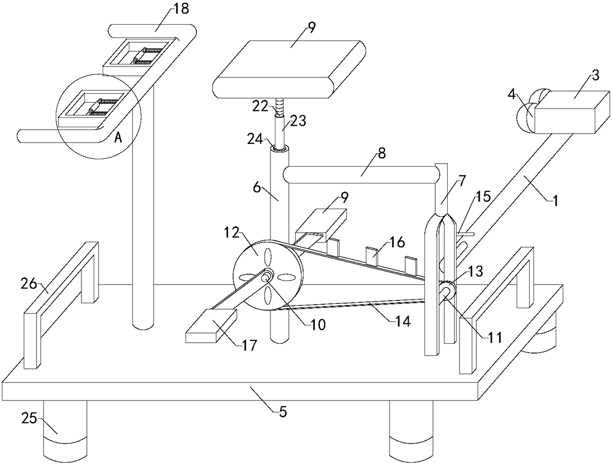
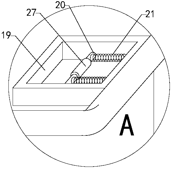
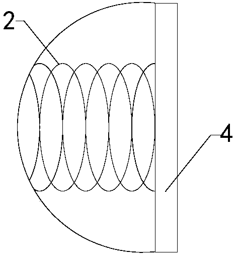
[0015] Such as Figure 1 to Figure 3 Shown, a kind of simple and easy pedal type back massage machine of the present invention comprises connecting rod 1, two groups of first springs 2, hammer body 3, two groups of massage balls 4 and two groups of brackets, the top of connecting rod and hammer body Two sets of brackets are respectively fixed on the front side wall and rear side wall of the hammer body, two sets of massage balls are respectively installed on the left ends of the two sets of brackets, two sets of first springs are respectively installed in the two sets of massage balls; Also includes base plate 5, one group of left support frame 6, one group of right suppo...


PUM


Abstract

The invention relates to the technical field of massage physiotherapy equipment, in particular to a simple pedal type back pounding massage machine. The massage machine is convenient to use, lower inuse limitation and higher in practicality, has various working modes and can effectively provide a user with appropriate exercise, and the physiotherapy effect is higher, so that the use reliability of the massage machine is improved. The massage machine comprises a connecting rod, two first springs, a hammer, two massage balls and two supports, wherein the two massage balls are arranged at the left ends of the two supports respectively; the massage machine further comprises a left support frame, a right support frame, a connecting frame, a strut, a cushion, a first rotating shaft, a second rotating shaft, a driving gear, a driven gear, a chain, a telescopic rope and a plurality of clamping plates, the chain is nested on the driving gear and the driven gear, and the plurality of clamping plates are all mounted on the chain; the massage machine also comprises a supporting rod, a handlebar, two tension plates, two pushing rods and two groups of second springs, and the two tension platesare arranged on the front side and the rear side of the left side wall of the handlebar respectively.

Description

technical field [0001] The invention relates to the technical field of massage physiotherapy equipment, in particular to a simple pedal-type back-beating massage machine. Background technique [0002] As we all know, the back-beating massage machine is a device that beats the appropriate parts of the back for people who are overtired and uncomfortable, so as to massage the user appropriately, thereby relieving the fatigue of the user, and is widely used in daily life. Existing back massager comprises connecting rod, two groups of springs, hammer body, two groups of massage balls and two groups of supports, the top of the connecting rod is connected with the bottom of the hammer body, and the two groups of supports are respectively fixed on the On the front side wall and the rear side wall of the hammer body, the two groups of massage balls are respectively installed on the left ends of the two groups of brackets, and the two groups of springs are respectively installed in th...

Claims


Application Information

Patent Timeline
Patent Type & Authority Applications(China)
IPC IPC(8): A61H23/00
CPCA61H23/006A61H23/004A61H2201/1253A61H2205/081
Inventor 何洋洋
Owner 何洋洋
Learn More