
Coiled type battery cell, battery cell coiling method and coiled battery

A wound-type battery cell technology, which is applied in the manufacture of primary batteries, wound/folded electrodes, and secondary batteries, can solve the problems of overlapping two tabs, low safety factor, and attenuation of battery performance. The probability of bending, the effect of reducing the risk of short circuit and increasing the distance

Inactive Publication Date: 2018-07-06
SHENZHEN RUILONG NEW ENERGY TECH
View PDF8 Cites 7 Cited by
  • Summary
  • Abstract
  • Description
  • Claims
  • Application Information

AI Technical Summary

Problems solved by technology

[0002] The two tabs of the existing battery are located on the innermost layer of the winding body, and the tab glue is also applied to the innermost layer of the winding body; when the battery is narrow and thick, due to the tab glue and the positions of the two tabs The limitation of the two tabs will cause the distance between the two tabs to be too small, or even overlap the two tabs
The small distance or overlap between two tabs increases the difficulty of the winding process, and at the same time, the safety factor is low, and there is a risk of short circuit
And when the battery is in use, the current will generate heat through the two tabs, and the winding body with the two tabs located at the innermost layer of the winding body is not easy to dissipate heat, especially when the battery is narrow and thick, the heat dissipation performance of the battery is even better. Not good, long-term use will cause rapid degradation of battery performance

Method used


Image

  • Coiled type battery cell, battery cell coiling method and coiled battery
  • Coiled type battery cell, battery cell coiling method and coiled battery
  • Coiled type battery cell, battery cell coiling method and coiled battery

Examples


Embodiment Construction

[0036] The principles and features of the present invention are described below in conjunction with the accompanying drawings, and the examples given are only used to explain the present invention, and are not intended to limit the scope of the present invention.

[0037] The present invention will be described below in conjunction with the accompanying drawings.

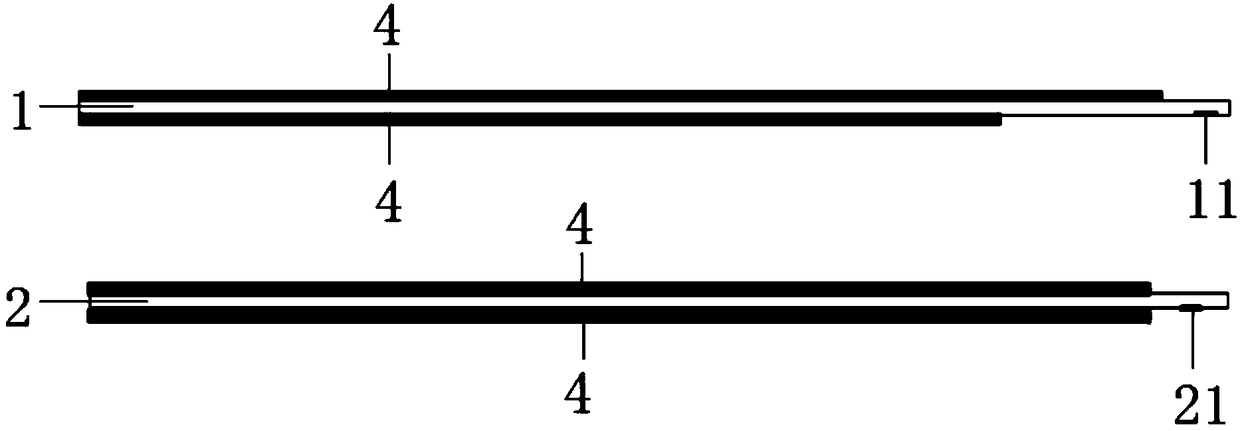
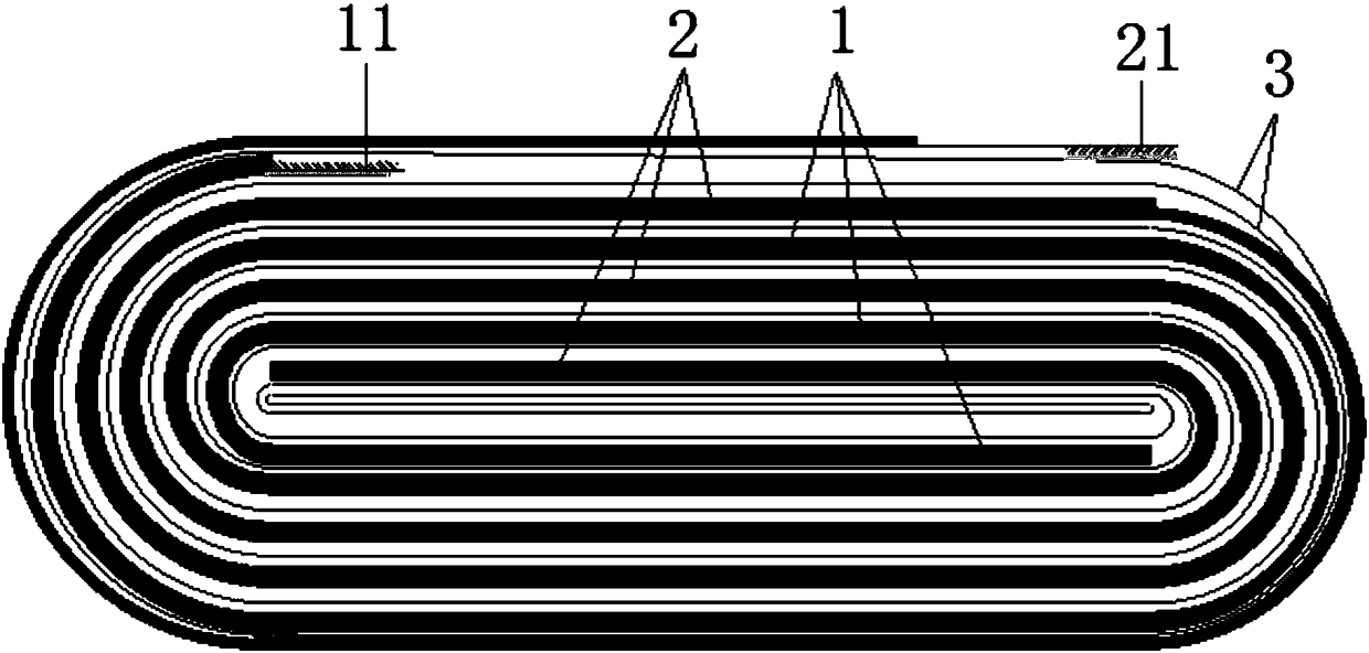
[0038] Such as figure 1 As shown, the embodiment of the present invention provides a winding battery, including a positive electrode sheet 1, a negative electrode sheet 2, and a separator 3 separating the positive electrode sheet 1 and the negative electrode sheet 2, figure 1 Diaphragm 3 is not shown in . The separator 3 is arranged between the positive electrode sheet 1 and the negative electrode sheet 2, one end of the positive electrode sheet 1 is provided with a positive electrode tab 11, one end of the negative electrode sheet 2 is provided with a negative electrode tab 21, the The end of the positive electro...


PUM


Abstract

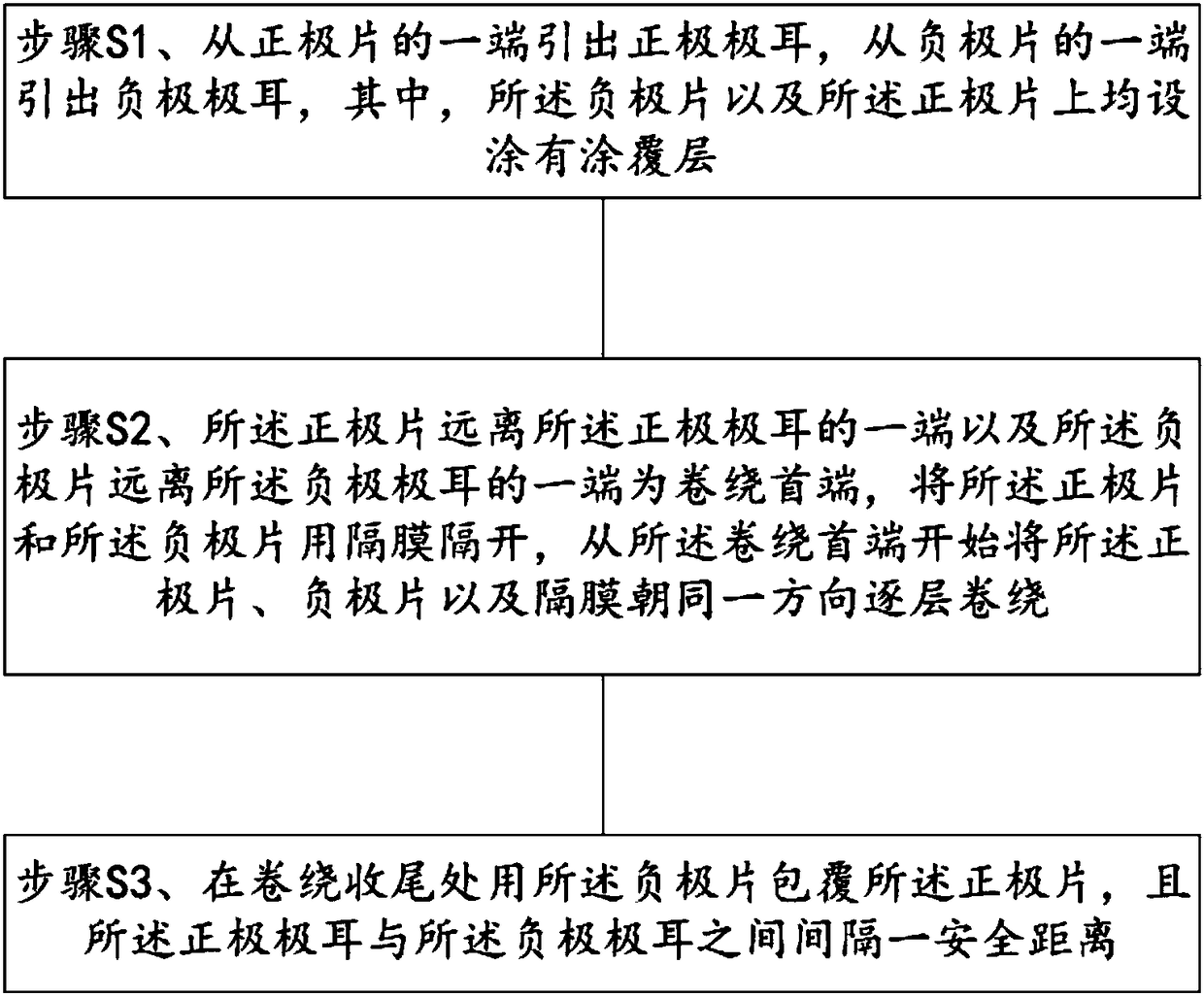
The invention relates to a coiled type battery cell which is characterized by comprising an anode piece, a cathode piece and a diaphragm, wherein the diaphragm is used for partitioning the anode piecefrom the cathode piece; both the anode piece and the cathode piece are coated with coating layers; the diaphragm is arranged between the anode piece and the cathode piece; an anode lug is arranged atone end of the anode piece; a cathode lug is arranged at one end of the cathode piece; one end, far away from the anode lug, of the anode piece, and one end, far away from the cathode lug, of the cathode piece are first coiling ends; the anode piece, the cathode piece and the diaphragm are coiled from the first coiling ends layer by layer in the same direction; the anode piece is wrapped by the cathode piece at the tail coiling end; and a safe distance is formed between the anode lug and a cathode lug. According to the coiled type battery cell provided by the invention, the distance between the anode lug and the cathode lug is increased by changing the coiling direction, the risk of short circuit can be reduced, heat radiation of a battery can be facilitated, and the performance of the battery can be improved.

Description

technical field [0001] The invention relates to the technical field of electric core winding, in particular to a method for electric core winding. Background technique [0002] The two tabs of the existing battery are located on the innermost layer of the winding body, and the tab glue is also applied to the innermost layer of the winding body; when the battery is narrow and thick, due to the tab glue and the positions of the two tabs The limitation of the two tabs will cause the distance between the two tabs to be too small, or even overlap the two tabs. The small distance or overlap between two tabs increases the difficulty of the winding process, and at the same time, the safety factor is low, and there is a risk of short circuit. And when the battery is in use, the current will generate heat through the two tabs, and the winding body with the two tabs located at the innermost layer of the winding body is not easy to dissipate heat, especially when the battery is narrow ...

Claims


Application Information

Patent Timeline
IPC IPC(8): H01M10/04H01M6/00
CPCH01M6/00H01M10/0431Y02E60/10Y02P70/50
Inventor 杨亮梁东建韦水凌李哲
Owner SHENZHEN RUILONG NEW ENERGY TECH
Learn More