
Spiral evaporator and running method thereof

A spiral evaporator and spiral technology, applied in the field of machinery, can solve problems such as uneven condensation and freezing, poor cooling effect, and low usage rate of refrigerant dosage, so as to achieve the effect of improving the effect and uniformity, and improving the utilization rate of coolant

Active Publication Date: 2018-07-06
青岛华友冰雪制冷工程有限公司
View PDF4 Cites 0 Cited by
  • Summary
  • Abstract
  • Description
  • Claims
  • Application Information

AI Technical Summary

Problems solved by technology

The existing refrigeration shafts all use nozzles to make the refrigerant contact the drum evaporator, but the length of the drum evaporator is too long, resulting in poor spraying and contact cooling effect, low refrigerant dosage and uneven condensation and freezing, etc. question

Method used


Image

  • Spiral evaporator and running method thereof
  • Spiral evaporator and running method thereof

Examples


Embodiment Construction

[0020] The following are specific embodiments of the present invention and in conjunction with the accompanying drawings, the technical solutions of the present invention are further described, but the present invention is not limited to these embodiments.

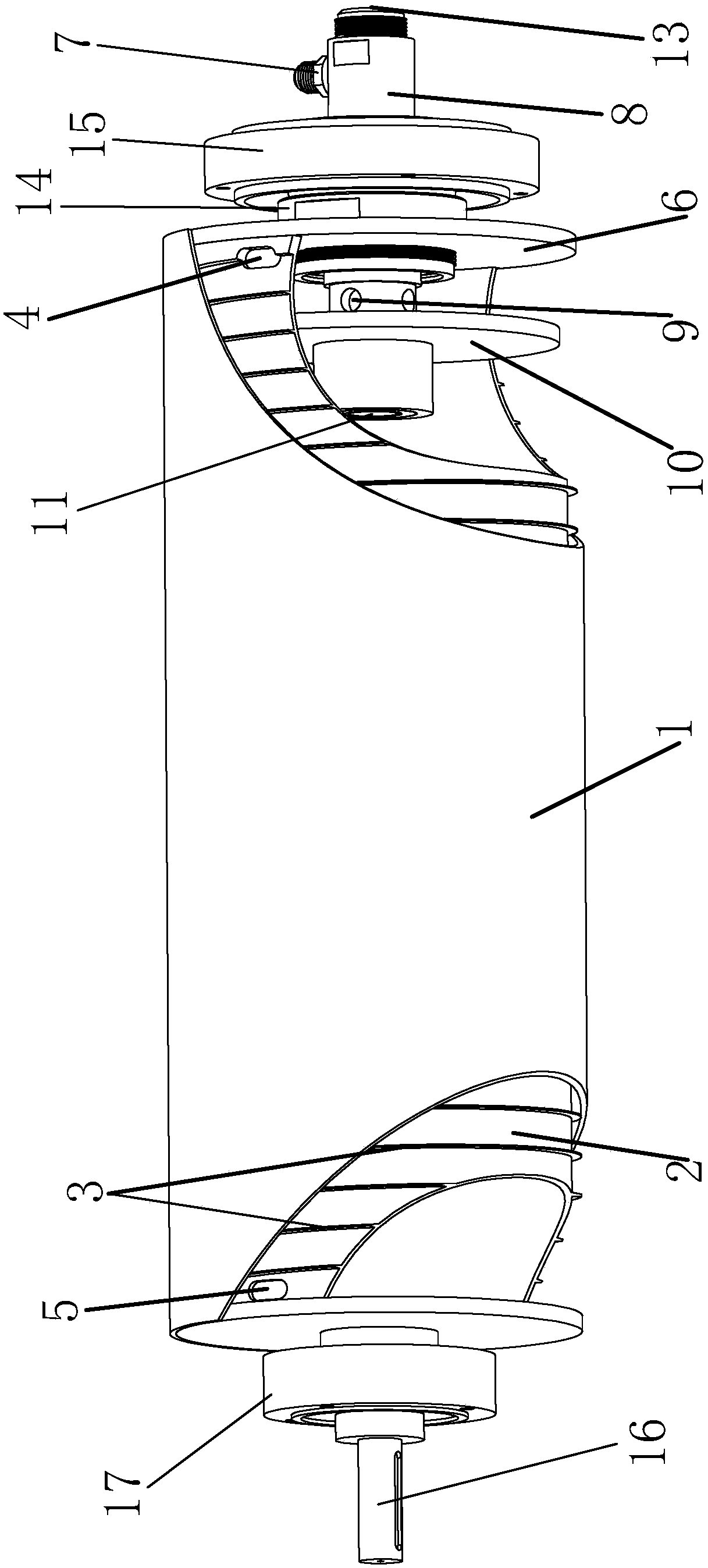
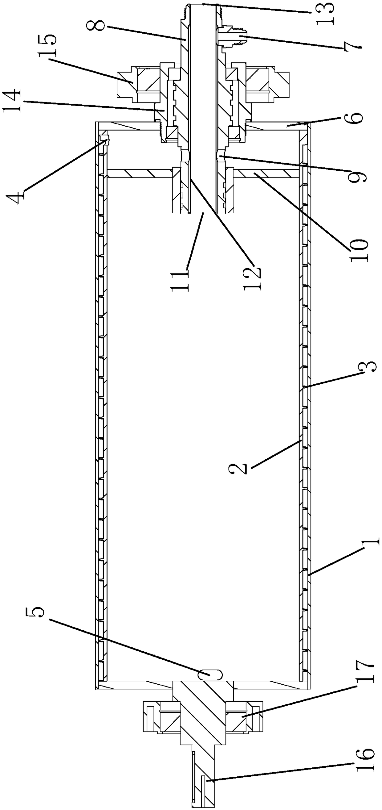
[0021] Such as figure 1 and figure 2 As shown, the spiral evaporator includes a drum shell. One end of the drum shell is a closed end, and the other end is provided with a baffle 6. The center of the baffle 6 has an opening. The drum shell includes a cylindrical shell 1 and a spiral inner shell. 2. A spiral wall 3 is provided on the outer wall of the spiral inner shell 2, and the bottom of the spiral wall 3 is fixedly connected to the spiral inner shell 2. The top of the spiral wall 3 forms a close connection with the inner wall surface of the cylindrical shell 1. Through The spiral inner shell 2, the spiral wall 3 and the cylindrical shell 1 are combined to form a spiral flow channel extending in the spiral direction of...


PUM

PropertyMeasurementUnit
Lengthaaaaaaaaaa

Abstract

The invention provides a spiral evaporator and a running method thereof. The spiral evaporator comprises a roller shell. The roller shell comprises a cylinder outer shell and a spiral inner shell. A spiral edge wall is arranged on the outer wall of the spiral inner shell. A spiral runner extending in the spiral direction of the roller shell is formed through splicing of the spiral inner shell, thespiral edge wall and the cylinder outer shell. A feeding hole is formed in one end of the spiral runner, a discharging hole is formed in the other end of the spiral runner, a refrigeration shaft piece stretches into the roller shell through a through port, and the inner section, stretching into the roller shell, of the refrigeration shaft piece is fixedly sleeved with an isolation plate, and a sealing chamber is formed between the isolation plate and a baffle and communicates with the feeding hole of the spiral runner. The refrigeration shaft piece is of a double-layer casing pipe structure with an outer pipe and an inner pipe. The outer end of the outer pipe is provided with a feeding port, the tail end, stretching into the roller shell, of the outer pipe is provided with an inlet hole,and an inner port, stretching into the roller shell, of the inner pipe is a material return port, wherein the material return port communicates with an inner cavity of the roller shell. The inner cavity of the roller shell communicates with the discharging hole of the spiral runner, and an outer port of the inner pipe is a discharging port.

Description

technical field [0001] The invention belongs to the technical field of machinery, and relates to snowmaking equipment, in particular to a spiral evaporator and its operation method. Background technique [0002] The Snow Drifter is a device for making snow crystals for use in snowy sets. It can realize snowmaking operation above zero, and the speed of snowmaking is fast, and it can realize snow entertainment projects in different seasons, and it plays a great role in film shooting and entertainment activities. [0003] Since the snow blowing machine needs to perform a large-scale snowfall effect, the specification of the drum evaporator in the equipment must reach the required length. The existing refrigeration shafts all use nozzles to make the refrigerant contact the drum evaporator, but the length of the drum evaporator is too long, resulting in poor spraying and contact cooling effect, low refrigerant dosage and uneven condensation and freezing, etc. question. Conten...

Claims


Application Information

Patent Timeline
IPC IPC(8): F25C1/12F25B39/02
CPCF25B39/02F25C1/12
Inventor 独孤勇
Owner 青岛华友冰雪制冷工程有限公司
Learn More