Single-drive control invisible connecting device

A connecting device and a single-drive technology, which is applied in the direction of connecting members, specially improved connectors and screws for tensile loads, can solve the problems of affecting appearance and cumbersome operation, and achieve the effect of easy disassembly and assembly and guarantee of perfection

Active Publication Date: 2018-07-06
GUILIN UNIVERSITY OF TECHNOLOGY
View PDF7 Cites 0 Cited by
  • Summary
  • Abstract
  • Description
  • Claims
  • Application Information

AI Technical Summary

Problems solved by technology

[0002]Screws, bolts and other fasteners are widely used in various types of equipment, and have formed a complete series of standards and become general-purpose parts in the industry; but such fasteners Restricted by the way of operation, some fasteners need to be exposed by the working part to facilitate the disassembly and assembly of the working tools, which leads to the protruding of many fasteners being worked on the outside of the connected parts. In order to avoid interference with such Fasteners need to process corresponding process bottom holes on the connected parts, especially in the field of large wooden, rubber-plastic and aluminum parts. The traditional fastening connection method is not only cumbersome to operate but also affects the appearance; therefore, a new type of The fastening connection operation method can not only solve the seamless fastening of many large components, but also facilitate disassembly and assembly without affecting the appearance, so as to ensure the integrity of the original product design and the perfection of multi-part connection

Method used


Image

  • Single-drive control invisible connecting device
  • Single-drive control invisible connecting device
  • Single-drive control invisible connecting device

Examples


Embodiment Construction

[0025] In order to make the technical means, creative features, objectives and effects achieved by the present invention easy to understand, the present invention will be further described below in conjunction with specific illustrations.

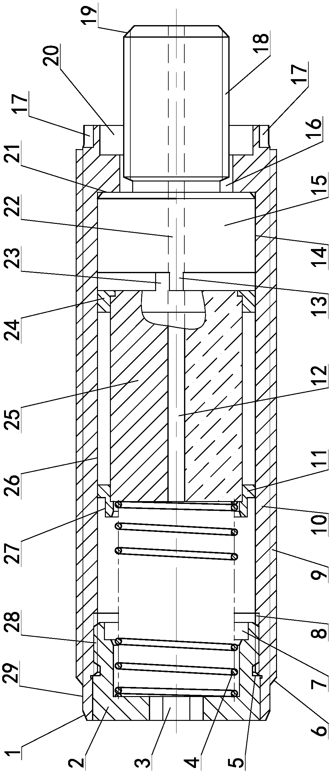
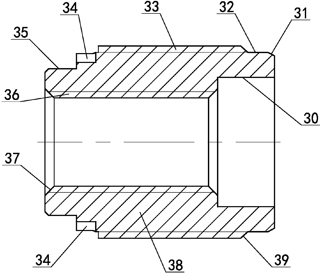
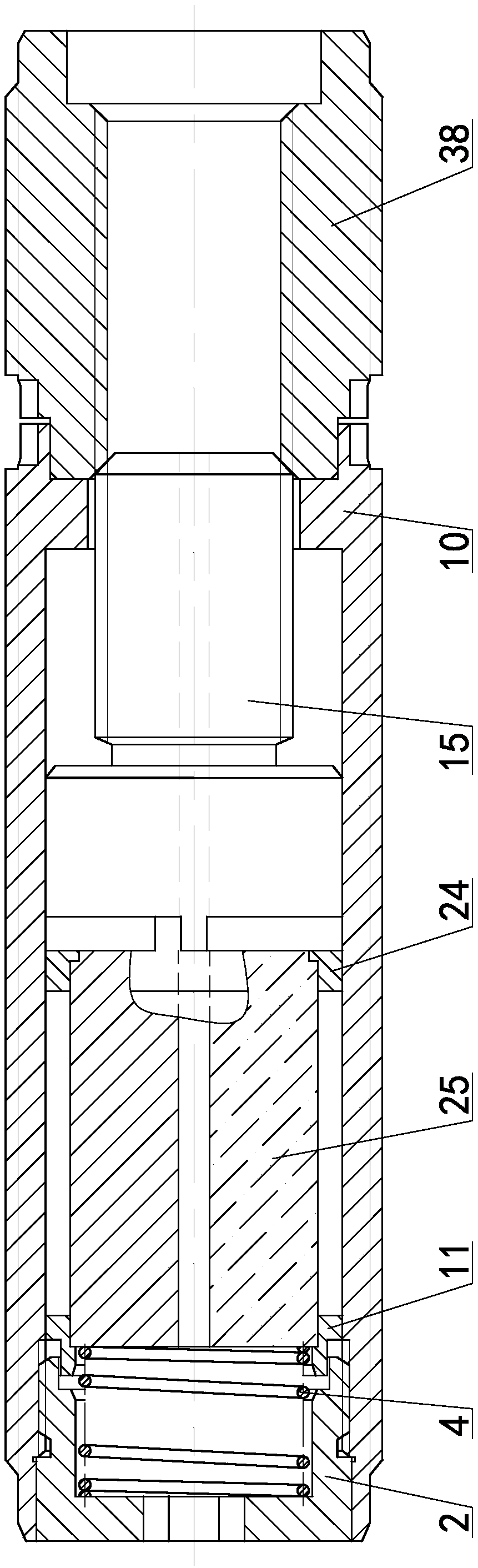
[0026] see Figure 1 ~ Figure 4 The single-drive control invisible connection device includes the first guide cone surface 1, the screw plug 2, the screw plug inner hexagon 3, the return spring 4, the screw plug limit end surface 5, the second guide cone surface 6, and the screw plug inner cavity hole 7 , main drive internal thread 8, main drive external thread 9, main drive body 10, drive magnet rear end bracket 11, first through hole 12, driven convex pin 13, bolt body matching outer circle 14, connecting bolt body 15, main Drive body connection channel 16, main drive body installation groove 17, plug external thread 18, plug body guide cone surface 19, main drive body connection cavity 20, main drive inner ring end face 21, second throug...


PUM


Abstract

A single-drive control invisible connecting device comprises a main drive body for invisibly connecting a first connected body with a second connected body and a secondary connecting body; one end ofthe main driving body is provided with a main drive outside thread and a main drive inside thread, and the other end is provided with a main drive installing slot, a main drive connecting inner cavityand a main drive body connecting channel; a screw plug is arranged at one side of the main drive body, and a driving magnet body and a main drive body inner ring end face for contacting with a connecting bolt body are arranged in the main drive body; one end of the periphery of the drive magnet body is provided with a drive magnet back end bracket, and the other end is provided with a drive magnet front end bracket; an active convex pin is arranged on the drive magnet front end bracket, one side of the drive magnet body is provided with the connecting bolt body, and the other side is providedwith a reset spring; a driven convex pin is arranged on the connecting bolt body; the invisible connection between the connected bodies is realized through the forward single drive of the installingdriving mechanism; when the installing driving mechanism is reversely driven, the connected bodies are separated so as to guarantee the perfection of the original product design.

Description

technical field [0001] The invention relates to the field of fastener connection technology, in particular to a single-drive control invisible connection device. Background technique [0002] Fasteners such as screws and bolts are widely used in various types of equipment, and have formed a complete series of standards and become common parts in the industry; It is exposed to the outside, which is convenient for working tools to disassemble and disassemble, which leads to a lot of fasteners being operated outside the connected parts. In order to avoid interference with such fastened parts, it is necessary to process corresponding process bottom holes on the connected parts , especially in the field of large wooden, rubber, plastic and aluminum parts, the traditional fastening connection method is not only cumbersome to operate but also affects the appearance; therefore, a new fastening connection operation method is needed, which can solve the problem of many large component...

Claims


Application Information

Patent Timeline
Patent Type & Authority Applications(China)
IPC IPC(8): F16B35/02F16B25/02F16B31/00
CPCF16B31/00F16B35/002F16B35/02F16B2031/002
Inventor 曹卫华张烈平
Owner GUILIN UNIVERSITY OF TECHNOLOGY
Why Eureka
Try Eureka