Eureka AIR delivers breakthrough ideas for toughest innovation challenges, trusted by R&D personnel around the world.

External culvert structure adapted to variable incoming flow angle low loss adjustable support plate

A culvert and angle technology, applied in the direction of machines/engines, jet propulsion devices, etc., can solve the problems of large geometric curvature, large flow loss of the second culvert strut, and large thickness of the second culvert strut

Inactive Publication Date: 2018-07-06
AECC SICHUAN GAS TURBINE RES INST
View PDF5 Cites 7 Cited by
  • Summary
  • Abstract
  • Description
  • Claims
  • Application Information

AI Technical Summary

Problems solved by technology

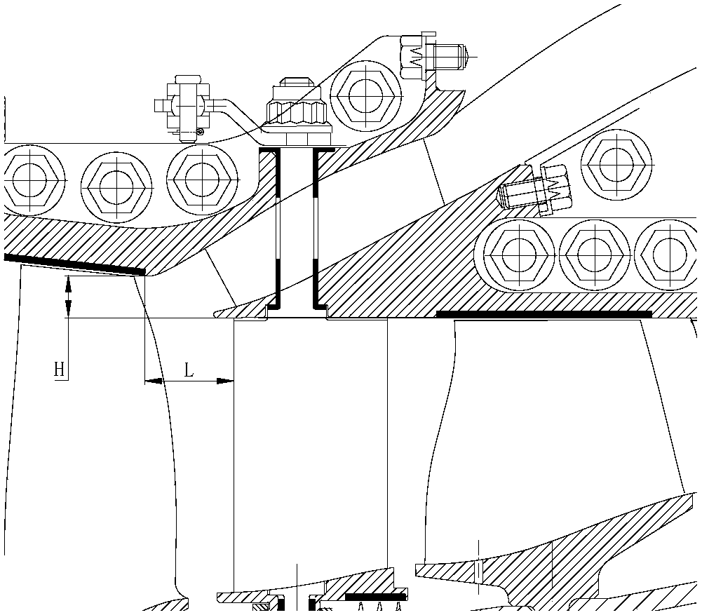
[0003] In a variable cycle engine, it is necessary to bleed air between the CDFS and the high-pressure compressor. Since the amount of bleed air is generally large, the conventional air bleed method in the compressor ( Figure 4 ) is to open a small slot on the compressor casing, and the air flow enters the air collection chamber through the slot and is drawn out. This method is more suitable for a small bleed air volume, and the bleed air loss is large, and it is not suitable for CDFS and high-pressure compressors. bleed air
The existing second connotation entraining air in China ( image 3 ) whose inlet is located between the outlet of the CDFS rotor and the inlet of the guide vane of the high-pressure compressor. The second outer culvert support plate has a large geometric curvature and is fixed in the second outer culvert flow channel
Since the second outer culvert strut has a large thickness and a large geometric curvature, and is fixed in the second outer culvert flow channel, the flow loss of the second outer culvert strut is relatively large when the airflow angle at the inlet of the second outer culvert changes in a large range in the circumferential direction , which is not conducive to the performance matching of various components of the variable cycle engine

Method used


Image

  • External culvert structure adapted to variable incoming flow angle low loss adjustable support plate
  • External culvert structure adapted to variable incoming flow angle low loss adjustable support plate
  • External culvert structure adapted to variable incoming flow angle low loss adjustable support plate

Examples


Embodiment Construction

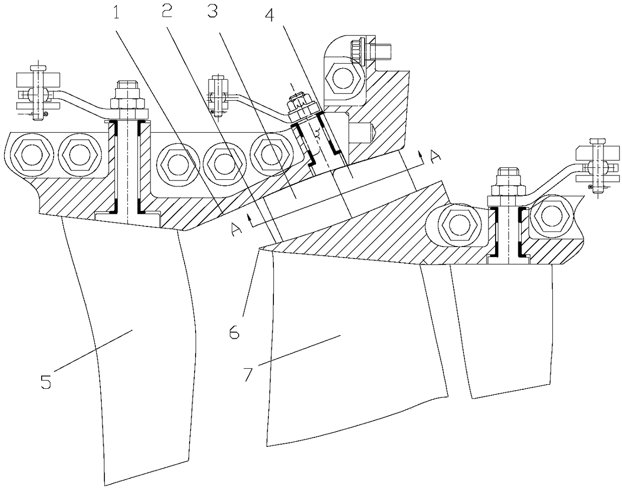
[0014] Re-select the position of the inlet section of the second outer culvert, and set the inlet of the second outer culvert on the casing between the outlet of the CDFS stator (5) and the inlet of the high-pressure compressor rotor (7), inside the support plate of the second outer culvert There is no longer an adjustment shaft passing through, and the thickness of the support plate of the second outer culvert is reduced, which is beneficial to reducing the flow loss in the second outer culvert.

[0015] The difference between the axial width and the radial height at the inlet of the second outer culvert is small, and the area of ​​the inlet of the second outer culvert must be increased as much as possible under the premise of ensuring a uniform flow field at the inlet of the high-pressure compressor. In the design of the second outer culvert runner, there is a certain angle between the second outer culvert runner and the axial direction, and the radial height of the second ou...


PUM


Abstract

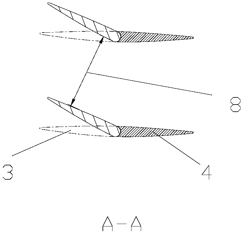
The invention belongs to the field of design of a core drive fan and a high pressure compressor in a gas turbine type engine, and provides an external culvert structure adapted to a variable incomingflow angle low loss adjustable support plate. A second external culvert inlet is located on a casing between the outlet of a CDFS (5) and the inlet of a high pressure compressor rotor (7), and an external culvert support plate of a second external culvert adopts a segmented adjustable structure. According to the external culvert structure adapted to the variable incoming flow angle low loss adjustable support plate, the second external culvert between the CDFS and the high pressure compressor is redesigned, and the inlet position of the second external culvert, an upper flow passage of the second external culvert, a lower flow passage of the second external culvert and a support plate structure of the second external culvert are specially designed, so that the air entraining content requirement under different bypass ratios can be realized under the condition that the high pressure compressor has better quality of an inlet flow field; and the flow losses in the second external culvertcan be well controlled under different incoming flow angles to ensure the better quality of an outlet flow field of the second external culvert.

Description

technical field [0001] The invention belongs to the technical field of air-bleeding of the second outer culvert of a convenient cycle engine, and in particular relates to an outer culvert structure adapting to variable flow angles and low loss adjustable support plates. Background technique [0002] In variable cycle engines, switching between different thermodynamic cycles can be realized by changing the bypass ratio. Performance has a vital impact on the overall performance of an aeroengine. In the process of bypass ratio change, accurately and efficiently realize the bleed air volume between CDFS and high-pressure compressor under different bypass ratios, and match the flow rate between CDFS and high-pressure compressor, which is the key to realize the switching between different thermodynamic cycles of the engine premise. [0003] In a variable cycle engine, it is necessary to bleed air between the CDFS and the high-pressure compressor. Since the amount of bleed air is...

Claims


Application Information

Patent Timeline
IPC IPC(8): F02K3/04F02K3/075
Inventor 米攀黄磊陈乾明安利平潘小娟李晓军刘治呈
Owner AECC SICHUAN GAS TURBINE RES INST
Why Eureka
Eureka Blog
Learn More