Straw biomass granulator

A biomass pellet and pellet machine technology, which is applied in the fields of biofuel, die extrusion pelletization, waste fuel, etc., can solve the problems of waste of raw materials and low production capacity, and achieve the effect of good energy saving, high production capacity and precise coordination.

Pending Publication Date: 2018-07-06
庞中化
View PDF4 Cites 5 Cited by
  • Summary
  • Abstract
  • Description
  • Claims
  • Application Information

AI Technical Summary

Problems solved by technology

The existing granulator is not equipped with a heating system. When starting up, it needs lubricating material to lubricate and preheat the machine. When the machine is turned off, the waste accumulated at the discharge port will easily lead to waste of raw materials, and the preheating time is longer than 20 minutes. The production capacity is also relatively low after startup

Method used


Image

  • Straw biomass granulator
  • Straw biomass granulator
  • Straw biomass granulator

Examples


Embodiment 1

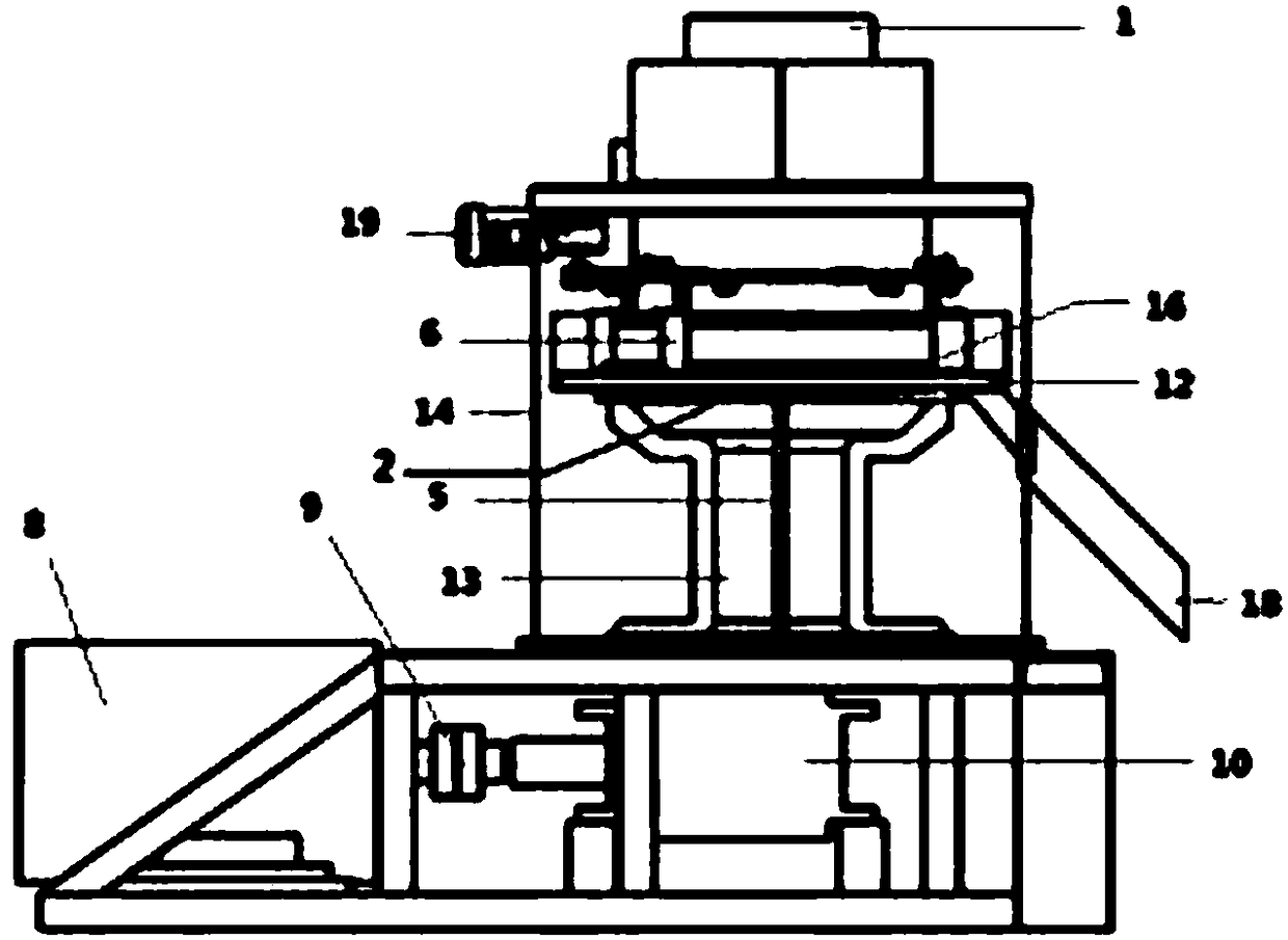
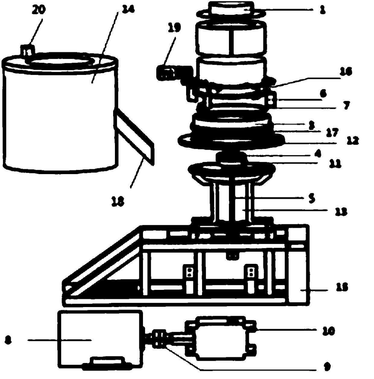
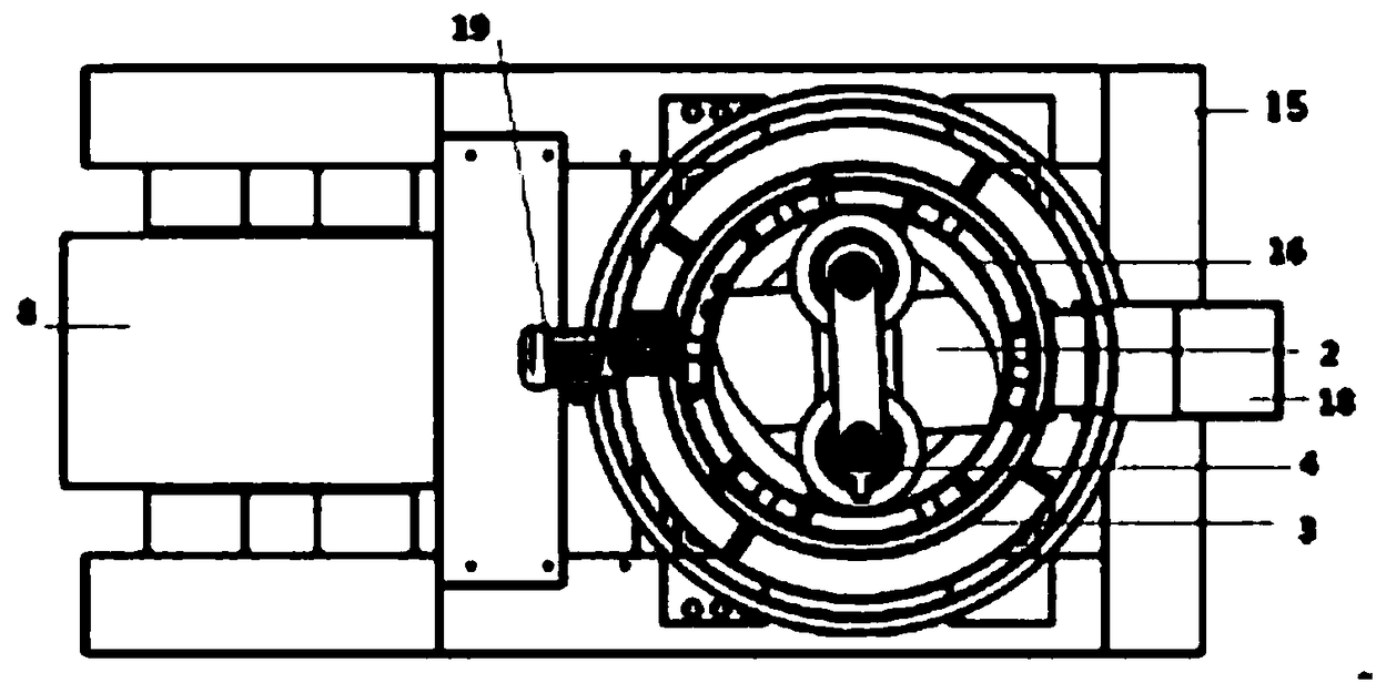
[0041] Such as figure 1 , figure 2 , image 3 , Figure 4 , Figure 5 , Image 6 , Figure 7 As shown, a biomass pellet machine includes a feed port 1, a turning plate 2, a ring die assembly 3, a pressing wheel 4 and a pressing wheel 11 through an eccentric shaft, an eccentric shaft adjusting ring, a connecting plate spline and a connecting plate Connected to the power system and set within the circumference of the ring die assembly 3. The main shaft 5 coincides with the axis of the ring die assembly 3. A scraper 6 is provided on the outside of the ring die assembly 3. After the material enters the feed port, the main motor 8 The speed reducer 10 and the main shaft 5 drive the press wheels 4 and 11 to rotate, feed the material into the gap between the press wheel and the ring die assembly, and scrape the particles formed in the ring die hole by the scraper 6, and then discharge the material. At the same time, the dust is removed through the dust removal interface 20.

[0042] T...

Embodiment 2

[0048] Similar to Example 1, the difference is that there is no heating element compression flange 16 above the ring mold, and a heating element 17 is provided below the ring mold assembly 3, and a groove is provided at the lower part of the ring mold assembly 3 for placement The heating element 17, the groove and the annular mold bottom plate 12 together prevent the heating element from contacting the dry material, thereby causing safety hazards.

[0049] The heating element 17 adopts an electric heating rod.

Embodiment 3

[0051] Similar to Embodiment 1, the difference is that a heating element 7 is provided above the ring die assembly 3, and a heating element 17 is provided below. Corresponding to the upper and lower parts of the ring die assembly 3, grooves are provided for placing the heating element 7 Together with 17, the groove, the compression flange 16 and the annular mold bottom plate 12, prevent the electric heating element from contacting the dry material and cause safety hazards.

[0052] Both heating elements 7 and 17 use electric heating rods.


PUM


Abstract

The invention discloses a straw biomass granulator which comprises a feeding port, a material turning plate and an annular mold assembly, wherein the material turning plate is located below a pressureroller assembly and is mechanically connected with a bottom supporting plate; the pressure roller assembly is arranged within a circumference of a mold assembly by a spindle; the spindle coincides with an axis of the mold assembly; a scraper is arranged below the pressure roller assembly; heating elements are arranged above and / or below the annular mold assembly; a groove is formed in an upper part of the annular mold assembly; the groove, a compressing flange and an annular mold base plate act together to prevent the heating elements from directly contacting dry materials to cause a fire andother safety hazards; the heating elements can be an electrical heating rod or PTC; the straw biomass granulator provided by the invention is further provided with a power system which comprises a motor and a speed reducer connected with the motor by a coupling; and the spindle is connected to the speed reducer. The straw biomass granulator provided by the invention has a yield increased by about30% compared with products having the same power in the market, and expands a range of water content of compressed materials to 25%; experimental tests show that a 55 kW granulator provided by the invention has properties superior to those of a 90 kW granulator in the market.

Description

Technical field [0001] The invention relates to an agricultural machinery and equipment, in particular to a straw biomass pellet machine. Background technique [0002] In the 1990s abroad, some countries in Europe, America, and Asia used biomass compact fuels in a large amount in their daily life. From the late 1990s to the present stage, countries led by Denmark have carried out research on large-scale utilization. The famous Danish energy investment company BWE took the lead in successfully developing the first biomass compact fuel power plant. The United States processes and exports straw as an important resource, and has achieved full mechanized processing, and some have achieved factory production. But the direction of U.S. straw utilization is not as fuel, but as feed or other industrial raw materials. The method of collecting straw is from the field, and the main technology is "straw bundling" technology. Japan began to study the application of mechanical piston molding ...

Claims


Application Information

Patent Timeline
Patent Type & Authority Applications(China)
IPC IPC(8): B01J2/22C10L5/44
CPCB01J2/22C10L5/445C10L2290/32Y02E50/10Y02E50/30
Inventor 庞中化
Owner 庞中化
Why Eureka
Try Eureka