
Drive mechanism

A technology of driving mechanism and metal components, which is applied in the direction of cameras, instruments, installation, etc., can solve the problems of easy damage and insufficient mechanical strength of the driving mechanism, and achieve the effect of minimizing the size of the driving mechanism

Active Publication Date: 2021-08-31
TDK TAIWAN
View PDF15 Cites 0 Cited by
  • Summary
  • Abstract
  • Description
  • Claims
  • Application Information

AI Technical Summary

Problems solved by technology

[0003] Since the camera lens module has tended to be miniaturized in recent years, it is extremely necessary to reduce the volume of its driving mechanism, but this often leads to the problem of insufficient mechanical strength of the driving mechanism and easy damage

Method used


Image

  • Drive mechanism
  • Drive mechanism
  • Drive mechanism

Examples


Embodiment Construction

[0079] The electromagnetic driving module of the embodiment of the present invention is described below. It should be readily appreciated, however, that the embodiments of the invention provide many suitable inventive concepts that can be implemented in a wide variety of specific contexts. The specific embodiments disclosed are merely illustrative of specific ways to use the invention and do not limit the scope of the invention.

[0080] Unless otherwise defined, all terms (including technical and scientific terms) used herein have the same meaning as commonly understood by one of ordinary skill in the art to which this disclosure belongs. It is understood that these terms, such as those defined in commonly used dictionaries, should be interpreted as having a meaning consistent with the background or context of the related art and the present disclosure, rather than in an idealized or overly formal manner Interpretation, unless specifically defined herein.

[0081] Please al...


PUM


Abstract

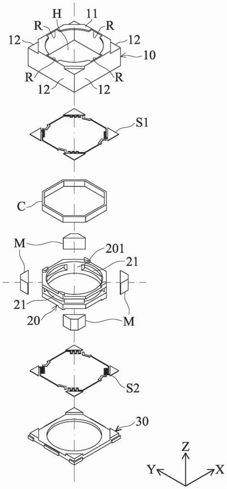
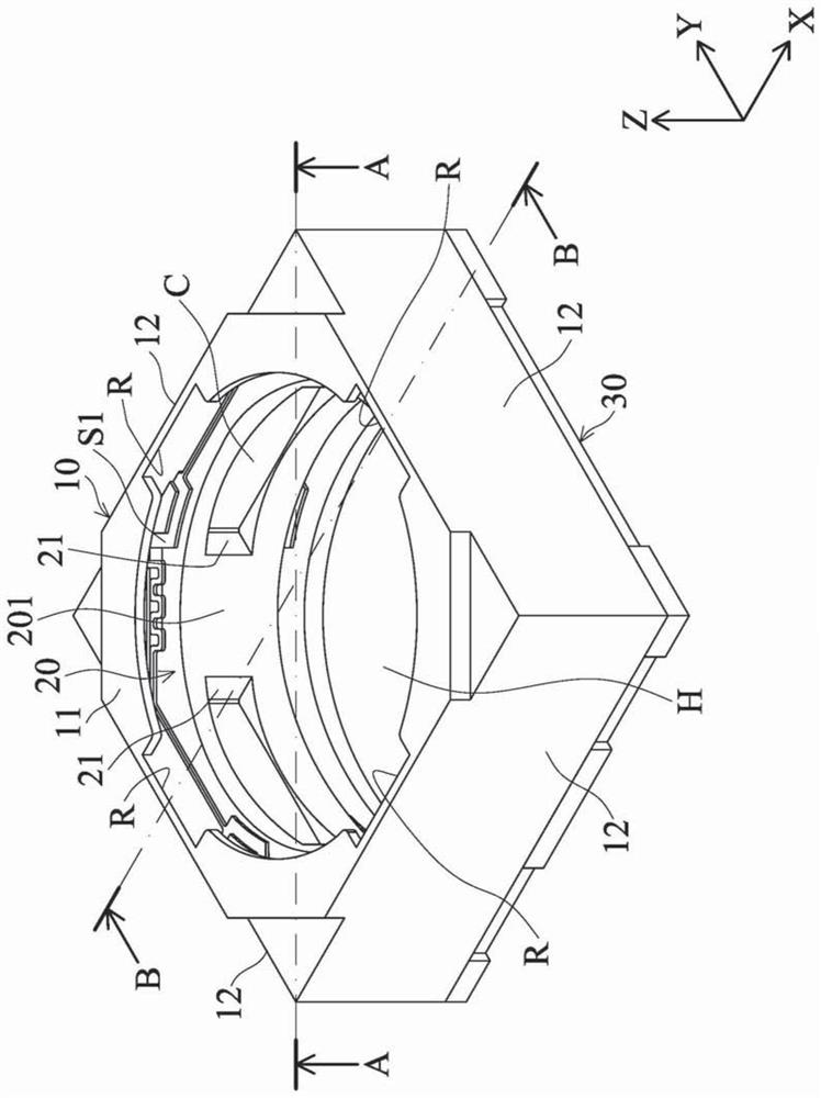
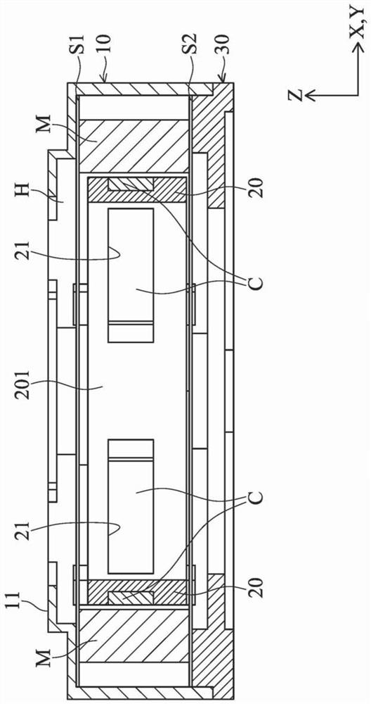
A driving mechanism is used to drive an optical assembly, and the driving mechanism includes an outer frame module, a bearing part and an electromagnetic driving assembly. The carrying part is arranged in the outer frame module for accommodating the optical components, wherein the carrying part has a side wall part, and a through hole is formed in the side wall part. The electromagnetic driving assembly includes a first magnetic assembly and a second magnetic assembly, wherein the first magnetic assembly is arranged on the bearing part and exposed inside the bearing part through a hole. The second magnetic component is connected with the frame module and corresponds to the first magnetic component, and is used for driving the carrier to move relative to the frame module.

Description

technical field [0001] The present invention relates to a driving mechanism, in particular to a driving mechanism capable of moving an optical component by electromagnetic force. Background technique [0002] With the rapid development of communication technology, camera lens modules have been widely used in portable electronic devices such as mobile phones and tablet computers. However, in order to improve the quality of photos taken by the camera lens module, it is usually equipped with an electromagnetic drive mechanism to adjust the position of the optical lens to achieve the functions of autofocus and / or zoom. shows a clear image. [0003] Since the camera lens module has tended to be miniaturized in recent years, it is extremely necessary to reduce the volume of its driving mechanism, but this often leads to the problem that the mechanical strength of the driving mechanism is insufficient and easily damaged. In view of this, how to reduce the size of the aforemention...

Claims


Application Information

Patent Timeline
Patent Type & Authority Patents(China)
IPC IPC(8): G02B7/09G03B13/36
CPCG02B7/09G03B13/36
Inventor 吴富源黄诗婷聂奕心宋欣忠
Owner TDK TAIWAN
Learn More