A Grab Bucket Ultrasonic Positioning Method

A positioning method, ultrasonic technology, applied in positioning, using ultrasonic/sonic wave/infrasonic wave, radio wave measurement system, etc., can solve problems such as easy breakage of cables, mechanical wear of encoders, measurement errors, etc., so as to facilitate centralized monitoring and engineering Small amount of effect

Active Publication Date: 2020-11-20
SHANGHAI ANGFENG EQUIP TECH CO LTD +1
View PDF9 Cites 0 Cited by
  • Summary
  • Abstract
  • Description
  • Claims
  • Application Information

AI Technical Summary

Problems solved by technology

[0003] This positioning method has the following problems: 1. The encoder will produce mechanical wear during use, resulting in measurement errors; 2. The measurement results of the encoder need to be transmitted to the ground through cables, but the cart and trolley are moving parts. The cables connected to the moving parts are easy to break; 3. There is a phenomenon of track slipping during the operation of the cart and trolley, and the encoder cannot detect the displacement caused by the slipping of the track

Method used


Image

  • A Grab Bucket Ultrasonic Positioning Method
  • A Grab Bucket Ultrasonic Positioning Method
  • A Grab Bucket Ultrasonic Positioning Method

Examples


Embodiment

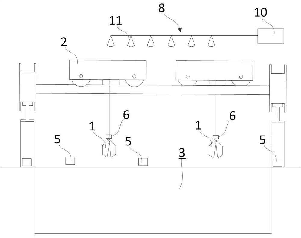
[0022] Example: such as figure 1 As shown, this embodiment specifically relates to a grab bucket ultrasonic positioning method, which is used to locate the position of the grab bucket; in this embodiment, two grab buckets 1 to be positioned are suspended above the garbage pool 3 by the garbage crane 2 , the garbage pool 3 and the space above it are the operating area of ​​the grab bucket 1 to be positioned; the garbage pool is 100m long and 25m wide; the method specifically includes the following steps:

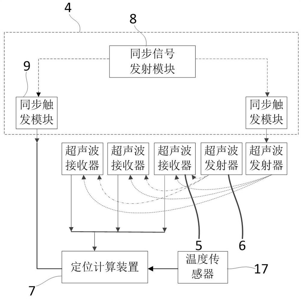
[0023] 1) if figure 1 , 2 As shown, a synchronization component 4 is installed, an ultrasonic transmitter 6 is installed on the grab bucket 1 to be positioned, and a positioning calculation device 7 and at least three ultrasonic receivers 5 are installed around the operating area of ​​the grab bucket to be positioned.

[0024] 1.1) If figure 1 , 2 As shown, the synchronization assembly 4 includes a synchronization signal transmitting module 8 and two synchronization trigg...

Embodiment 2

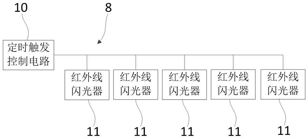
[0043] Embodiment 2: as Figure 4 , 5 As shown, the main difference between this embodiment and Embodiment 1 is that the synchronization signal in this embodiment is a radio pulse signal; in this embodiment, the synchronization signal transmitting module 8 includes a timing trigger control circuit 10 and a wireless pulse signal transmitter connected to each other 18; the wireless pulse signal transmitter 18 can send a synchronous signal under the control of the timing trigger control circuit 10; in order to be compatible with the synchronous signal transmitting module 8, the synchronous signal receiving module 12 in the synchronous triggering module 9 is a wireless pulse signal receiving device.


PUM


Abstract

The invention discloses an ultrasonic grab bucket positioning method. The ultrasonic grab bucket positioning method comprises the following steps: mounting a synchronizing component, mounting an ultrasonic transmitter on a to-be-positioned grab bucket, and mounting a positioning calculation device and at least three ultrasonic receivers at the periphery of an operating area of the to-be-positionedgrab bucket; enabling the ultrasonic transmitter to transmit an ultrasonic signal under trigger of the synchronizing component; measuring propagation time of the ultrasonic signal by the ultrasonic receivers and the positioning calculation device, and calculating position coordinates of the to-be-positioned grab bucket by the positioning calculation device according to the mounting position of each ultrasonic receiver and the measured propagation time. The ultrasonic grab bucket positioning method disclosed by the invention has the advantages that no mechanical equipment is needed, and regular maintenance operations such as abrasion, refueling and the like do not exist; errors brought by track skid and the like are avoided, so that a corresponding calibration device is not needed.

Description

technical field [0001] The invention belongs to the field of mechanical equipment, and in particular relates to an ultrasonic positioning method for a grab bucket. Background technique [0002] The traditional grab is usually suspended under the crane; in the prior art, the encoder distance measurement is usually used to locate the grab; during the positioning process, the X coordinate of the grab is detected by the encoder of the cart system, and encoded by the trolley system The sensor detects the Y mark of the grab bucket, and the Z coordinate of the grab bucket is provided by the winch system. The detected signal needs to be sent from the car to the big car and then sent to the ground. [0003] This positioning method has the following problems: 1. The encoder will produce mechanical wear during use, resulting in measurement errors; 2. The measurement results of the encoder need to be transmitted to the ground through cables, but the cart and trolley are moving parts. ...

Claims


Application Information

Patent Timeline
Patent Type & Authority Patents(China)
IPC IPC(8): G01S5/18G01B17/00
CPCG01B17/00G01S5/18
Inventor 朱宏敏戴至前朱宏兴杨松
Owner SHANGHAI ANGFENG EQUIP TECH CO LTD
Why Eureka
Try Eureka