Heat pump humidifying device and working method

A humidification device and heat pump technology, which can be used in heating methods, household heating, household heating, etc., can solve the problems of high operating cost, low relative humidity, and inability to work.

Active Publication Date: 2018-06-29
JIANGSU UNIV OF SCI & TECH
View PDF22 Cites 3 Cited by
  • Summary
  • Abstract
  • Description
  • Claims
  • Application Information

AI Technical Summary

Problems solved by technology

[0003] The existing humidification methods mainly include: isothermal humidification, isenthalpy humidification, cooling humidification, temperature increasing humidification, etc., and each has its own characteristics in terms of humidification devices. There are small electric heating, ultrasonic household humidifiers, large ultrasonic, wet film, Centrifugal industrial humidifiers, but the existing humidifiers have many shortcomings such as large power consumption, high operating costs, low energy efficiency, and large floor space
[0004] In the three seasons of spring, autumn and winter, the air is dry and the relative humidity is low. It is very necessary to increase the air humidity to increase the relative humidity to maintain the comfort of the air. Great progress has been made, but there are still many deficiencies in achieving the comfort of building air humidity efficiently and uniformly; in industrial production, humidity regulation is indispensable. Judging from the existing industrial humidification devices, there are many problems such as high energy consumption, The problem of low output, and some devices are greatly affected by the environment when they work, and even have the problem of not working. Therefore, it is necessary to build an efficient and economical humidification device for use in life and production.

Method used


Image

  • Heat pump humidifying device and working method

Examples


Embodiment Construction

[0031] In order to make the above objects, characteristics and advantages of the present invention more comprehensible, specific embodiments of the present invention will be described in detail below in conjunction with the accompanying drawings.

[0032] Furthermore, the directional terms mentioned in the present invention, such as "upper", "lower", "left", "right", "front", "inner", "top", "bottom", "upper left", "Upper right", etc., are only referring to the direction of the attached drawing. Therefore, the use of directional terms is used to illustrate and understand the present invention, but not to limit the present invention.

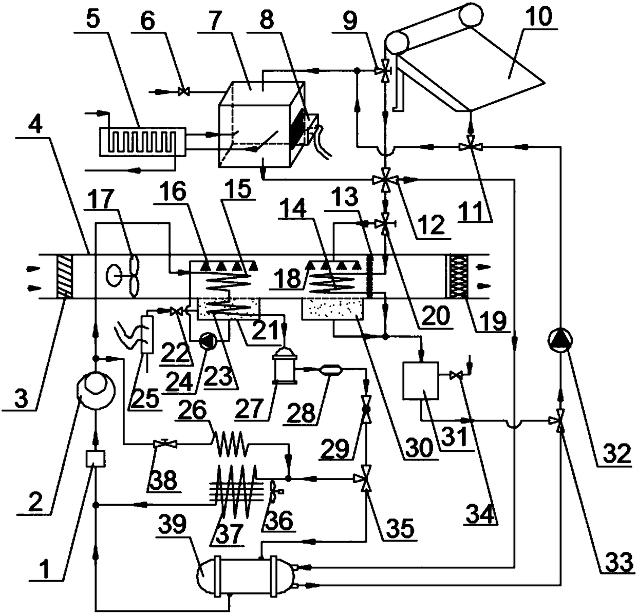
[0033] Such as figure 1 As shown, it is a heat pump humidification device according to an embodiment of the present invention, which includes three parts: a heat pump system, a solar heat collection system, and a spray air supply system, wherein the heat pump system includes: a gas-liquid separator 1, a compressor 2, a second A condensing coil ...


PUM


Abstract

The invention discloses a heat pump humidifying device and a working method. The heat pump humidifying device comprises a heat pump system, a solar heat collector and a spraying air supply system. Themethod is characterized by being dividing into three working modes according to the atmospheric environment temperature T0 and the water temperature difference Delta T of water at an inlet and an outlet of the solar heat collector, and the three working modes comprises A, the working mode in which the T0 is larger than or equal to 15 DEG C and the Delta T is larger than or equal to 30 DEG C; B, the working mode in which the T0 is larger than or equal to 15 DEG C and the Delta T is less than 30 DEG C; and C, the working mode in which the T0 is less than 15 DEG C and the Delta T is less than 30DEG C. According to the heat pump humidifying device and the working method, the heat pump technology is coupled with the solar heat collection technology, so that a heat pump and the solar heat collector are connected in series / in parallel to work, and the yield and preparation efficiency of steam are improved; and compared with an existing humidifying device, the device has the advantages of being high in steam yield, good in energy efficiency, economical in operation and wide in application range.

Description

technical field [0001] The present invention relates to a humidifying device, more specifically, to a heat pump humidifying device. It belongs to the technical field of air conditioning equipment. Background technique [0002] The humidity of the air is one of the "four degrees" of air conditioning. From the perspective of meeting the requirements of comfort and craftsmanship, ensuring that the air has an appropriate humidity value will be an important part of air conditioning. The phase value of air comfort is between 40% and 60%. The air in winter is relatively dry, and the humidity value of the air in the room will drop during the heating process, which makes people feel uncomfortable; it is used in printing and dyeing textiles, food processing, flowers In the typical industrial production such as horticulture and electronic chips, the maintenance of air humidity is also very important, which not only affects the output of industrial products, but also affects the qualit...

Claims


Application Information

Patent Timeline
IPC IPC(8): F24F3/14F24F5/00F24F13/30
Inventor 杨兴林李自强沈九兵张刘挺李志远邵明扬赵倩
Owner JIANGSU UNIV OF SCI & TECH
Why Eureka
Try Eureka