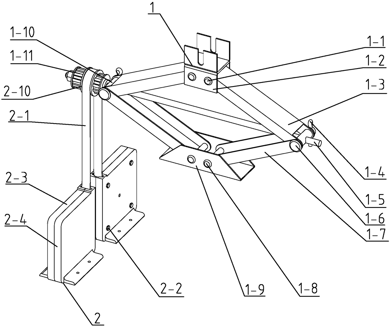
Force magnification driving device based on shape memory alloy
A memory alloy and driving device technology, applied in the direction of machines/engines, mechanisms that generate mechanical power, mechanical equipment, etc., can solve the problems of limited application scope, complex structure of force driving devices, and large resistance, so as to eliminate the need for locking and unlocking. Mechanism, mass reduction, overall weight reduction effect
- Summary
- Abstract
- Description
- Claims
- Application Information
AI Technical Summary
Problems solved by technology
Method used
Image
Examples
specific Embodiment approach 1
[0020] Specific implementation mode one: combine Figure 1 to Figure 7 Describe this embodiment, a force amplification drive device based on a shape memory alloy described in this embodiment includes a force amplification mechanism 1 and a shape memory alloy drive mechanism 2, and the force amplification mechanism 1 includes a top bracket 1-2, a screw 1-5, Threaded hole pin 1-6, base 1-9, light hole pin 1-10, spline shaft 1-11, two upper support arms 1-3 and two lower support arms 1-7, two lower supports The arms 1-7 are relatively arranged, the lower end of the lower support arm 1-7 is rotationally connected with the base 1-9, and the upper end of a lower support arm 1-7 is connected to the lower end of an upper support arm 1-3 through the light hole pin shaft 1-10 Hinged, the upper end of another lower support arm 1-7 is hinged with the lower end of another upper support arm 1-3 through threaded hole pin shaft 1-6, two upper support arms 1-3 are arranged oppositely, and uppe...
specific Embodiment approach 2
[0026] Specific implementation mode two: combination Figure 1 to Figure 2To illustrate this embodiment, one end of the screw 1-5 in this embodiment is provided with a shoulder, and the shoulder is caught on the outer peripheral side wall of the light hole pin 1-10. Other compositions and connection methods are the same as those in Embodiment 1.
[0027] One end of the screw rod 1-5 is designed in this way to be positioned by the shoulder of the screw rod 1-5, so that the relative position of the screw rod 1-5 and the pin shaft 1-10 of the light hole remains unchanged.
specific Embodiment approach 3
[0028] Specific implementation mode three: combination Figure 1 to Figure 4 To illustrate this embodiment, a thrust washer 1-14 is respectively provided on both ends of the spline shaft 1-11 in this embodiment, and the thrust washer 1-14 is set on the screw rod 1-5, and the spline shaft 1 The outside of the thrust washer 1-14 at the -11 outer side is provided with a nut 1-12, and the nut 1-12 is screwed on the end of one end of the screw rod 1-5, and the nut 1-12 is connected with the thrust washer at the outer side of the spline shaft 1-11 Spring washers 1-13 are provided between 1-14. Other compositions and connection methods are the same as those in the second embodiment.
[0029] In such a design, the splined shaft 1-11 and the light hole pin shaft 1-10 on one end of the screw rod 1-5 are effectively positioned.
PUM
 Abstract
Description
Claims
Application Information
 - R&D
- Intellectual Property
- Life Sciences
- Materials
- Tech Scout
- Unparalleled Data Quality
- Higher Quality Content
- 60% Fewer Hallucinations
Browse by: Latest US Patents, China's latest patents, Technical Efficacy Thesaurus, Application Domain, Technology Topic, Popular Technical Reports.
© 2025 PatSnap. All rights reserved.Legal|Privacy policy|Modern Slavery Act Transparency Statement|Sitemap|About US| Contact US: help@patsnap.com


