
Multipurpose interlocking valve

A multi-purpose, interlocking technology, applied in the direction of multi-way valves, sliding valves, valve devices, etc., can solve the problems of high quality requirements for personnel and difficult processing angles, and achieve small size, overcome medium penetration and leakage, and adaptability strong effect

Inactive Publication Date: 2002-04-03
胡高泉
View PDF4 Cites 0 Cited by
  • Summary
  • Abstract
  • Description
  • Claims
  • Application Information

AI Technical Summary

Problems solved by technology

However, the valve has relatively high requirements on the contact plane of the adjustment block, valve core, and valve seat sealing ring, and the processing angle of the positioning groove for the adjustment block to move up and down is difficult, and the manufacturing and maintenance require high quality of personnel, etc.

Method used


Image

  • Multipurpose interlocking valve
  • Multipurpose interlocking valve
  • Multipurpose interlocking valve

Examples


Embodiment

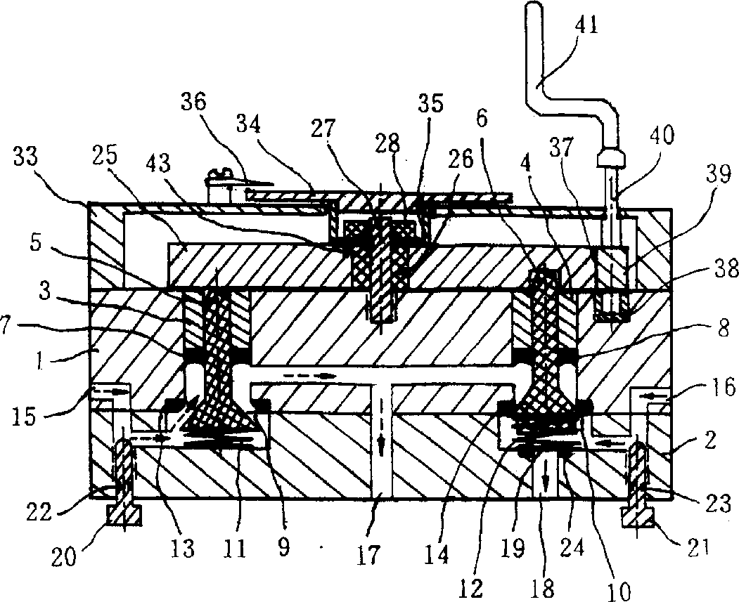
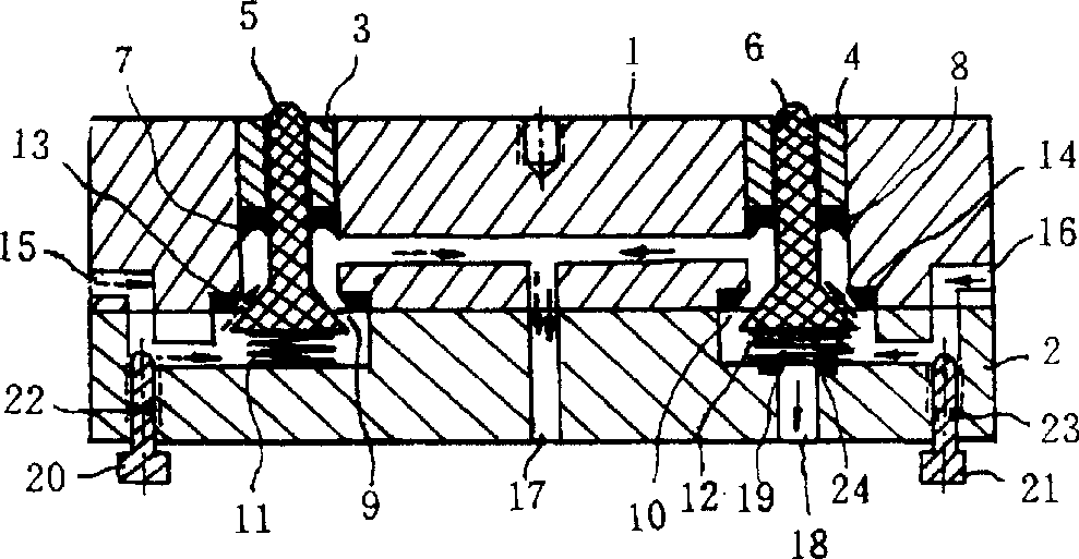
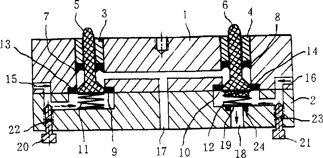
[0036] Multipurpose chain valve of the present invention is shown in accompanying drawing. There is an upper valve body 1, and the lower end of the upper valve body 1 is fixedly connected with the lower valve body 2. There are two shaft sleeves 3, 4 on the upper valve body 1, the shaft sleeves 3, 4 are equipped with up and down sliding cone valve cores 5, 6, and the lower ends of the shaft sleeves 3, 4 have herringbone sealing rings 7, 8. The lower ends of the conical spools 5,6 sliding up and down are connected with the springs 11,12 located in the valve ports 9,10. Valve ports 9 and 10 are provided with sealing seat rings 13 and 14 that are closely matched with the up and down sliding cone spools 5 and 6. Valve ports 9 and 10 have medium inlets 15 and 16 and medium outlets 17 and 18, and valve port 10 has a connected auxiliary valve port 19. Adjusting bolts 20, 21 for controlling the flow rate or pressure of various media are arranged on the channel communicating with the...


PUM


Abstract

A multipurpose interlocking valve is composed of upper and lower valve bodies, medium inlet and outlet, and rotary control disk which is arranged on the top of upper valve body and has at least one arc slot. Said lower valve body has at least two valve mouthes and at least two conic valve cores, which has top end matched with the arc slot of rotary control disk and bottom end positioned on spring in valve mouth of lower valve and can slide up and down in upper valve body. Said rotary control disk rotates around the central axle on upper valve body to exchange position with conic valve core, so allowing medium to flow. Its advantages are small size, compact structure and high reliability.

Description

(1) Technical field: [0001] The present invention relates to valves, especially multi-purpose interlock valves. (two) background technology: [0002] Existing multi-way valves are all made up of some fixed and movable valve parts. When the movable spool is switched to the valve position, the rotation between the valve positions will cause serious friction and the sealing parts will be severely worn. In order to overcome the leakage defect of this type of multi-way valve, the authorized notification number is CN2226179Y, which discloses a patent entitled "Anti-leakage and Low-wear Combination Valve". The patented technical solution consists of a valve seat, a valve core, an upper cover, and a valve core transposition mechanism. An adjustment block is arranged on the upper part of the valve core, and the adjustment block is supported on the valve seat by an elastic element. A pressure accumulation chamber is provided between the adjustment block and the upper cover, and the...

Claims


Application Information

Patent Timeline
Patent Type & Authority Patents(China)
IPC IPC(8): F16K3/08F16K11/14
Inventor 易秀文
Owner 胡高泉
Learn More