
Centrifugal atomization device

A centrifugal atomization and centrifugal disc technology, which is applied in the fields of air humidifiers, air purifiers, and air conditioners. It can solve the problem that water absorption and centrifugal disc speed cannot be controlled separately, and the acceleration of water droplets leaving the disc surface is low, which affects the effect of centrifugal atomization. and other problems, to achieve the effect of good atomization effect, good atomization effect and simple structure

Pending Publication Date: 2018-06-29
ZHONGSHAN RUICHI TAIKE ELECTRONICS CO LTD
View PDF0 Cites 10 Cited by
  • Summary
  • Abstract
  • Description
  • Claims
  • Application Information

AI Technical Summary

Problems solved by technology

[0003] 1. The thickness of the mist is uneven, and the proportion of fine water droplets is relatively large: the water absorption and the centrifugal turntable share a motor, and the water absorption and the speed of the centrifugal disk cannot be controlled separately. Excess will affect the effect of centrifugal atomization;
[0004] 2. The efficiency of single atomization is low: the centrifugal disc uses the method of raising the water level step by step, thinning it into a water film and tearing it into water filaments through centrifugal acceleration, and the water droplets are thrown out of the disc surface. The acceleration of water droplets leaving the disc surface is relatively low, resulting in atomization efficiency. Low;
[0005] 3. High noise: Under the existing atomization technology, in order to obtain better atomization effect, higher centrifugal acceleration is required, which requires higher motor speed, and the higher the motor speed, the greater the noise and vibration of the machine

Method used


Image

  • Centrifugal atomization device
  • Centrifugal atomization device
  • Centrifugal atomization device

Examples


Embodiment Construction

[0030] The present invention will be further described in conjunction with the accompanying drawings and specific embodiments. It should be understood that these examples are only used to illustrate the present invention and are not intended to limit the scope of the present invention. In addition, it should be understood that after reading the content taught by the present invention, those skilled in the art may make various changes or modifications to the present invention, and these equivalent forms also fall within the scope defined in the present application.

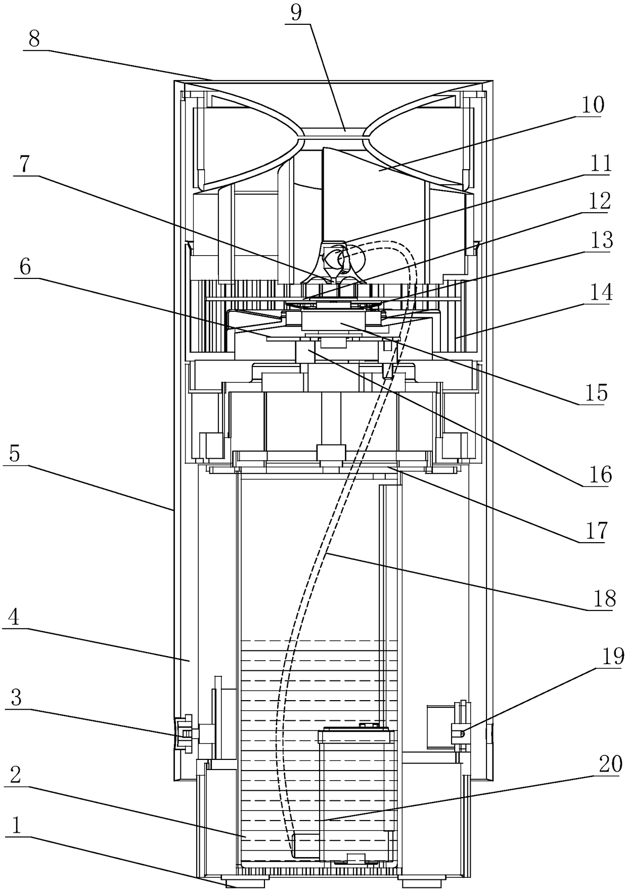
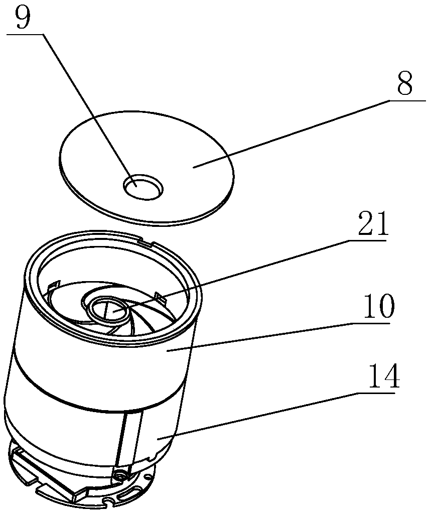
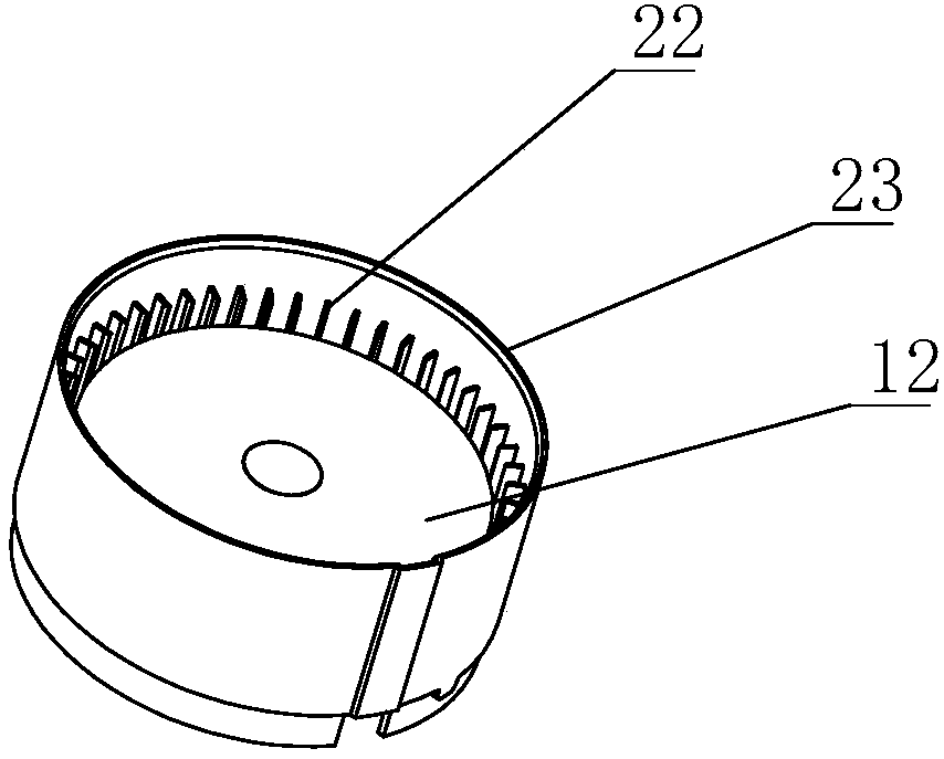
[0031] Such as Figure 1~6 As shown, a centrifugal atomization device includes a casing 5, a water tank 2, a water pump 20 and an atomizing mechanism are arranged inside the casing 5, and a control button 3, a power socket 19, an air inlet 4, and a casing 5 are also provided on the casing 5. A number of shock-absorbing rubber feet 1 are set at the bottom, and the atomization mechanism includes a centrifugal disc 1...


PUM


Abstract

The invention provides a centrifugal atomization device. The centrifugal atomization device comprises a shell, wherein a water tank, a water pump and an atomization mechanism are arranged in the shell; the atomization mechanism comprises a centrifugal plate, a motor driving the centrifugal plate to rotate and mist making grids; a water outlet is arranged above the centrifugal plate, the water pumpis connected with the water outlet through a water inlet pipe, and the mist making grids are arranged on the outer side of the centrifugal plate in the circumferential direction; a vortex cover is further arranged above the centrifugal plate; a plurality of vortex plates are arranged below the vortex cover; water is thrown out by the centrifugal plate, then impacts the mist making grids to form fine mist and then bounces back to the centrifugal plate, forming water mist airflow rotating along the plate surface of the centrifugal plate at a high speed; and the water mist airflow is guided by the vortex plates and then moves to the center of the centrifugal plate and rises to form spiral mist flow, and then the spiral mist flow is discharged from mist outlet holes formed in the shell. The centrifugal atomization device has the beneficial effects of being high in atomization efficiency and good in atomization effect, and is suitable for air humidifiers, air purifiers and other equipmentneeding atomization.

Description

technical field [0001] The invention mainly relates to the technical fields of air humidifiers, air purifiers and air conditioners, in particular to a centrifugal atomization device. Background technique [0002] In equipment such as air humidifiers and purifiers, atomization mechanisms are required. However, the atomization mechanism with traditional structure generally has the following problems: [0003] 1. The thickness of the mist is uneven, and the proportion of fine water droplets is relatively large: the water absorption and the centrifugal turntable share a motor, and the water absorption and the speed of the centrifugal disk cannot be controlled separately. The water absorption increases with the increase of the speed of the centrifugal disk. Excess will affect the effect of centrifugal atomization; [0004] 2. The efficiency of single atomization is low: the centrifugal disc uses the method of raising the water level step by step, thinning it into a water film a...

Claims


Application Information

Patent Timeline
IPC IPC(8): B05B3/08B05B12/00F24F6/16F24F13/24
CPCF24F6/16F24F13/24B05B3/082B05B12/00F24F2013/247
Inventor 刘胜森钱炳海李琦刘乐天
Owner ZHONGSHAN RUICHI TAIKE ELECTRONICS CO LTD
Learn More