
Multi-level expansion cavity sprayer

A technology of expanding cavity and nozzle, which is applied to spray devices, spray devices, chemical instruments and methods, etc., can solve the problems of low cleaning efficiency, easily damaged surface, incomplete dust removal, etc. simple effect

Pending Publication Date: 2018-06-29
ZHEJIANG SCI-TECH UNIV
View PDF8 Cites 3 Cited by
  • Summary
  • Abstract
  • Description
  • Claims
  • Application Information

AI Technical Summary

Problems solved by technology

[0002] Solar energy is a clean energy that is developed all over the world. The photovoltaic power generation industry is developing at an astonishing speed. However, photovoltaic panels are easy to accumulate dust during outdoor use, which will seriously affect the absorption and conversion efficiency of photovoltaic panels to sunlight. Therefore, photovoltaic panels must be inspected. regular cleaning
The commonly used cleaning method for photovoltaic panels is mechanical touch cleaning, that is, cleaning with cleaning devices such as rags. This method has the disadvantages of low cleaning efficiency and easy damage to the surface; non-contact gas cleaning methods are mostly fixed-frequency airflow impacts, It is easy to form a layer of mucous film on the surface of photovoltaic panels, and there is a problem of incomplete dust removal; in addition, efficient nanometer self-cleaning film materials can also be used to cover the surface of photovoltaic panels, but the cost is too high to be suitable for mass production; and electric curtain dust removal technology in Domestic research is less, and it has not been widely used

Method used


Image

  • Multi-level expansion cavity sprayer
  • Multi-level expansion cavity sprayer
  • Multi-level expansion cavity sprayer

Examples


Embodiment Construction

[0015] The present invention will be further described below in conjunction with the accompanying drawings, but the present invention is not limited to the following examples.

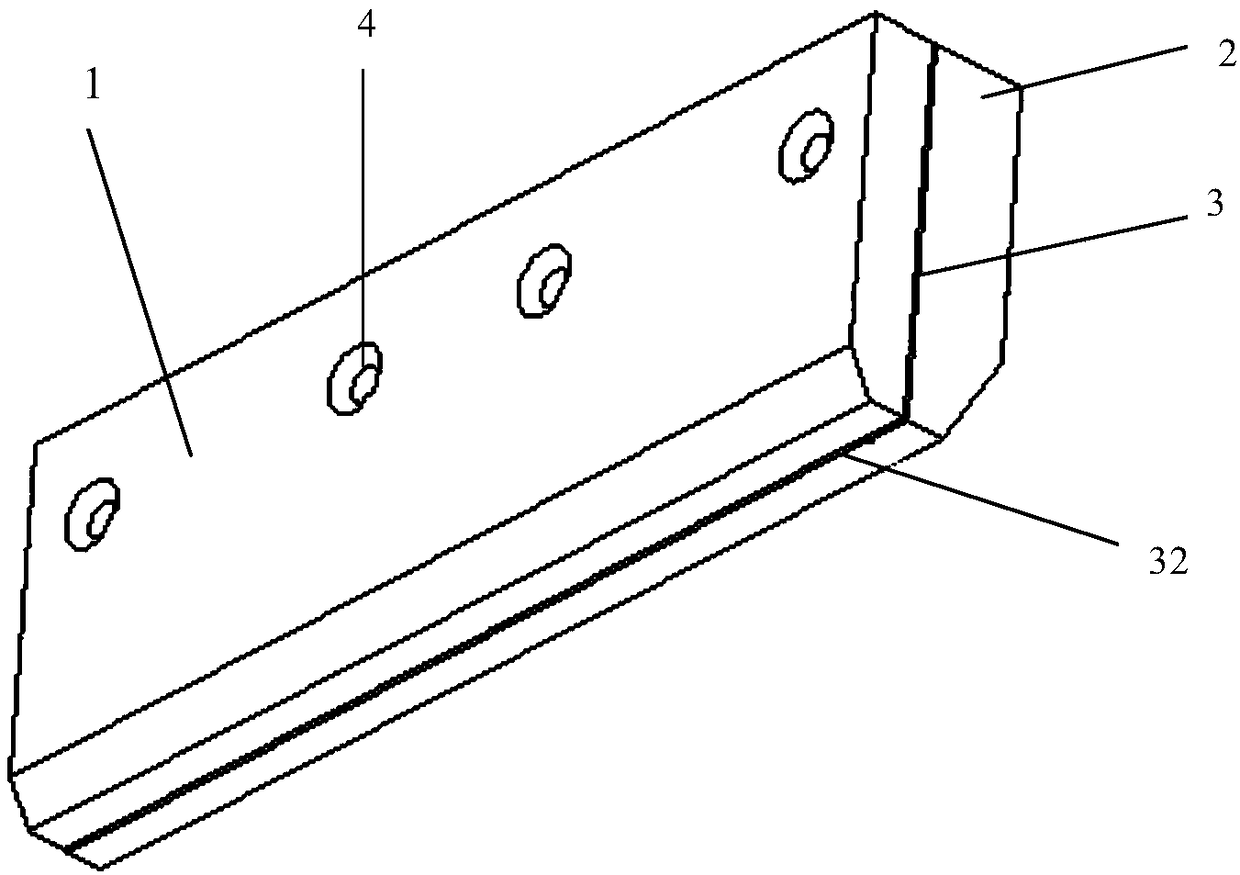
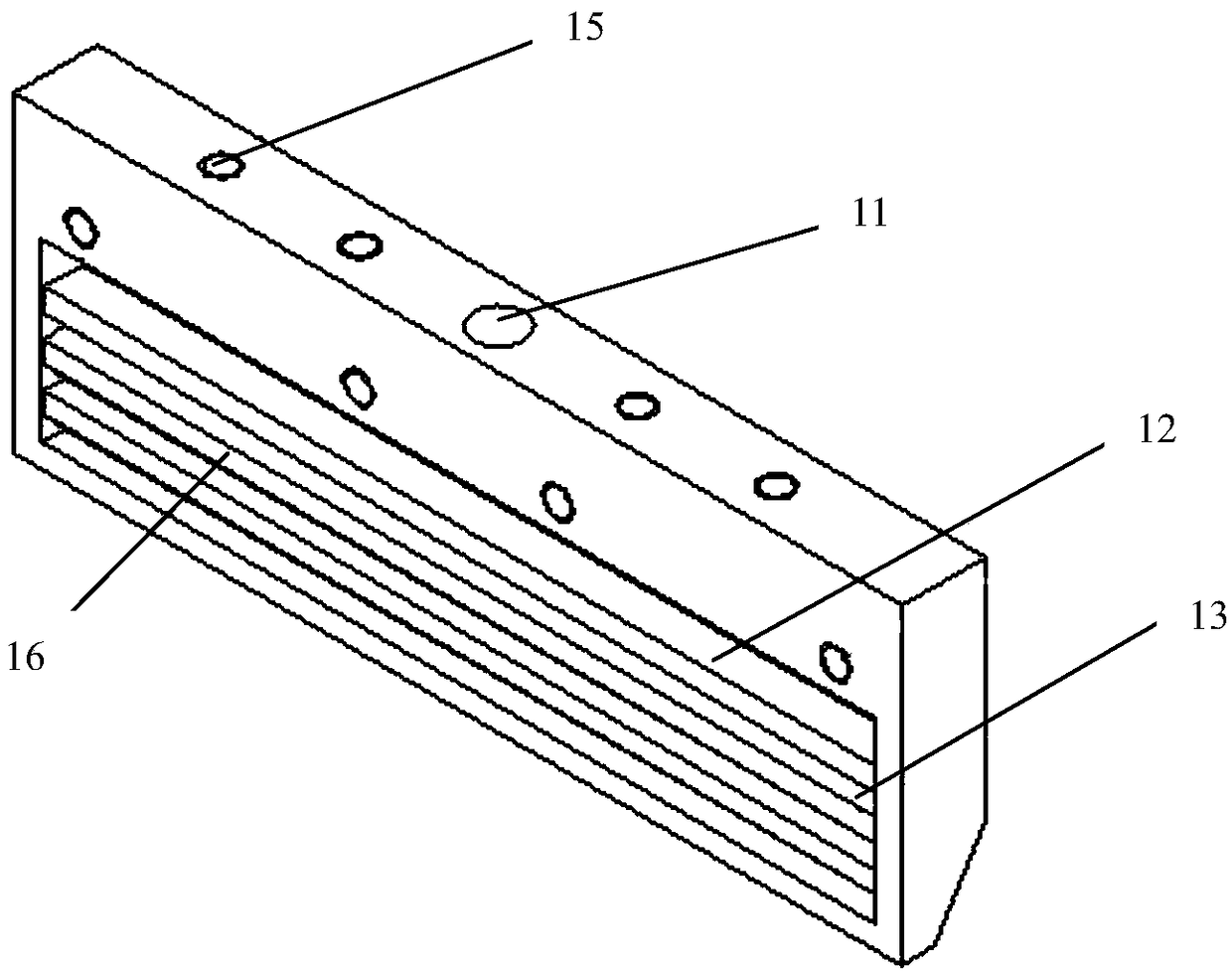
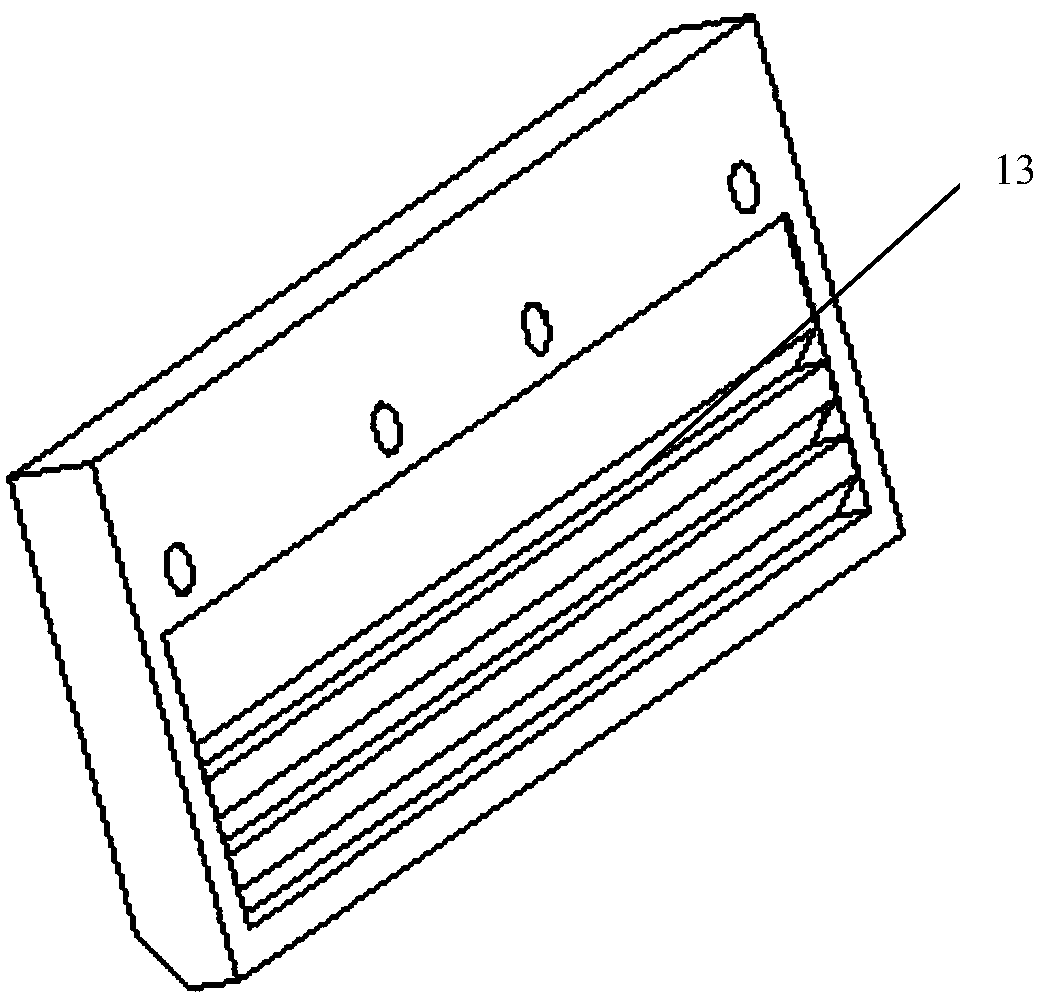
[0016] As shown in the figure, a multi-stage expansion cavity spray head includes a front casing 1, a rear casing 2 and a gasket 3 between the front casing and the rear casing, and the front casing, the rear casing and the gasket pass through The connecting piece 4 (usually a screw) is fixedly connected. The gasket is in the shape of a "door" surrounded by three sides, and the length and width are suitable for the front and rear shells. After the gasket is installed, a certain gap is formed between the front and rear shells as the airflow channel 31, and the opening side of the gasket is used as the airflow channel. Air outlet 32. A rectangular groove is formed on the side of the front housing facing the gasket. After the front housing and the rear housing are fixed, the rectangular groove forms an ai...


PUM


Abstract

The invention relates to a cleaning device, and aims at providing a multi-level expansion cavity sprayer. The sprayer can spray high-frequency turbulent flow, the situation that airflow impacts on a photovoltaic panel, and an adhering film is formed is avoided, and the beneficial effects of high efficiency and thorough dust removal are achieved. According to the technical scheme, the multi-level expansion cavity sprayer comprises front shells, a rear shell and n-shaped gaskets located between the front shells and the rear shell; the front shells, the rear shell and the gaskets are fixedly connected through connecting pieces; the face, facing the corresponding gasket, of each front shell is provided with a rectangular groove so that a rectangular air storage cavity temporally storing airflow can be formed, wherein an air inlet hole penetrating the wall part of the front shell for high-pressure gas input is formed above the rectangular groove; a plurality of right-angle triangular grooves are manufactured in the part, below the corresponding rectangular groove, of each front shell, and horizontally-arranged and mutually-parallel trapezoid columns arranged at the interval of a certaindistance in pairs are formed between every two right-angle triangular grooves and between the right-angle triangular grooves and the rectangular groove; and the rear shell is symmetrically provided with trapezoid columns, wherein the number of the trapezoid columns is the same with the number of the front shells, and the trapezoid columns correspond to the front shells in position.

Description

technical field [0001] The invention relates to a cleaning device, in particular to a multi-stage expansion cavity nozzle. Background technique [0002] Solar energy is a clean energy that is developed all over the world. The photovoltaic power generation industry is developing at an astonishing speed. However, photovoltaic panels are easy to accumulate dust during outdoor use, which will seriously affect the absorption and conversion efficiency of photovoltaic panels to sunlight. Therefore, photovoltaic panels must be inspected. Clean regularly. The commonly used cleaning method for photovoltaic panels is mechanical touch cleaning, that is, cleaning with cleaning devices such as rags. This method has the disadvantages of low cleaning efficiency and easy damage to the surface; non-contact gas cleaning methods are mostly fixed-frequency airflow impacts, It is easy to form a layer of mucous film on the surface of photovoltaic panels, and there is a problem of incomplete dust ...

Claims


Application Information

Patent Timeline
IPC IPC(8): B05B1/00B08B5/02
CPCB05B1/005B08B5/02
Inventor 杜小强姜丰刘恩晓
Owner ZHEJIANG SCI-TECH UNIV
Learn More