
Combined sickbed for patient operation transfer

A combined and patient-friendly technology, applied in the field of combined hospital beds for patient surgical transfer, can solve the problems of secondary injury to patients, insufficient flexibility of the hospital bed, and time-consuming patients, and achieve the effect of saving time and avoiding secondary injury

Active Publication Date: 2018-06-29
HUZHOU CENT HOSPITAL
View PDF4 Cites 7 Cited by
  • Summary
  • Abstract
  • Description
  • Claims
  • Application Information

AI Technical Summary

Problems solved by technology

[0005] The purpose of the present invention is to address the deficiencies of the prior art, by separating the ordinary hospital bed into a movable part and a fixed part that can be quickly disassembled and then overcomes that the existing surgical bed is not flexible enough, and the patient transfer process consumes a lot of time. It is necessary to move the patient from one bed to another during the transfer process, which may cause secondary injury to the patient

Method used


Image

  • Combined sickbed for patient operation transfer
  • Combined sickbed for patient operation transfer
  • Combined sickbed for patient operation transfer

Examples


Embodiment 1

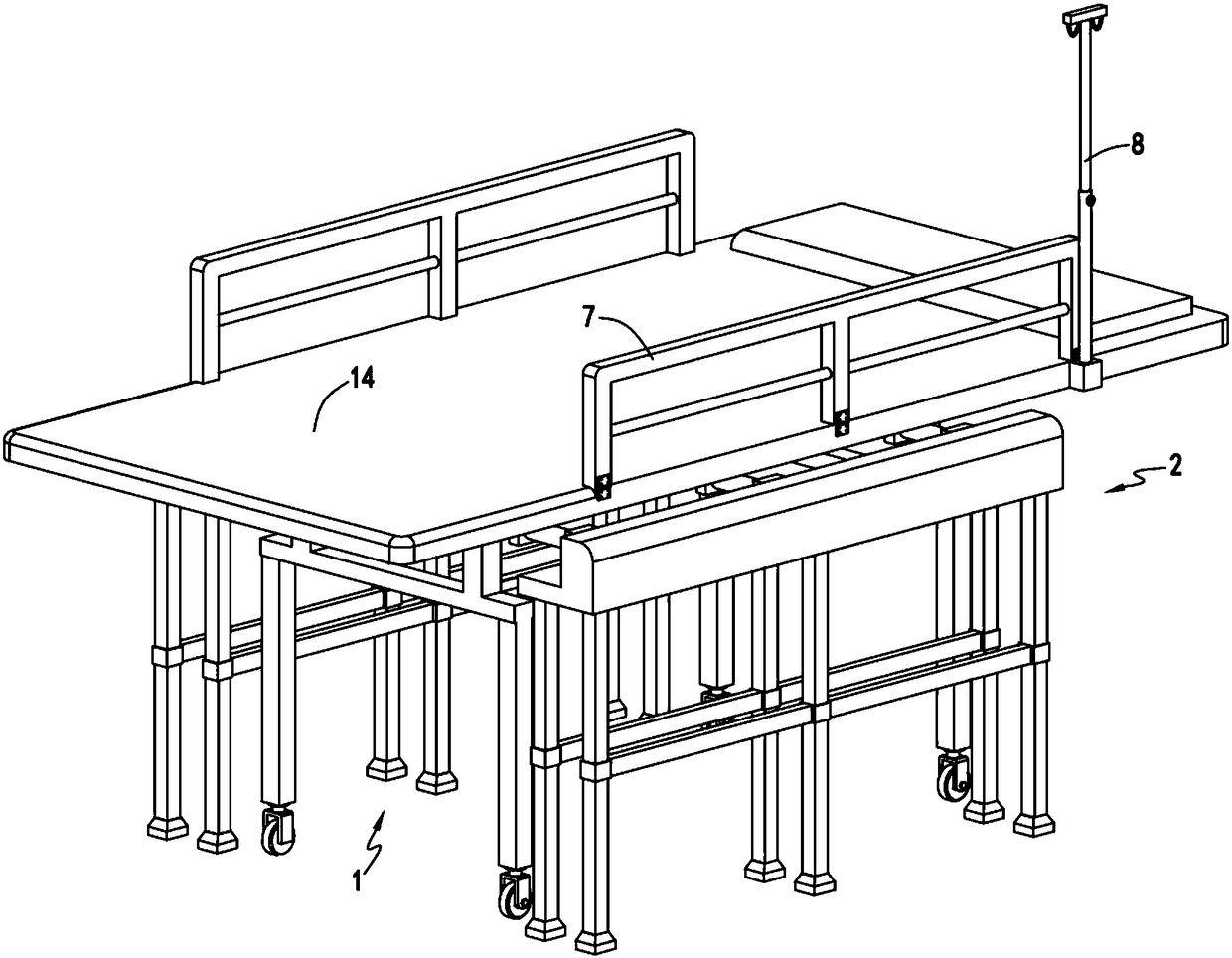
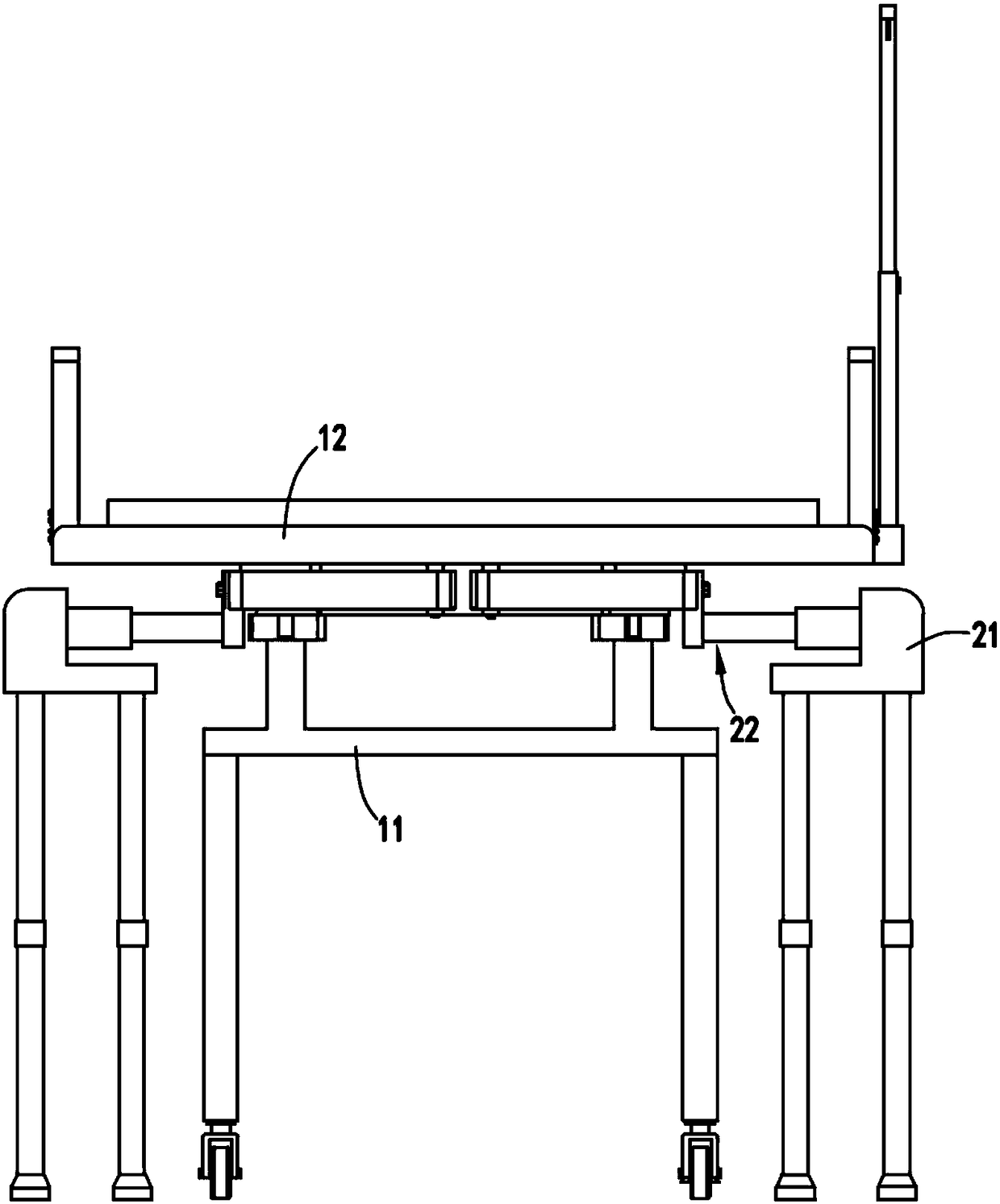
[0044] Such as figure 1 , figure 2 , image 3 , Figure 4 , Figure 5 , Image 6 , Figure 7 , Figure 8 , Picture 9 with Picture 10 As shown, a combined hospital bed for surgical transfer of a patient includes a moving part 1 for transferring a patient. The moving part 1 includes a walking frame 11, a bed body 14 mounted on the walking frame 11, and a bed The carrying device 12 under the body 14 and the disassembling device 13 provided on one side of the carrying device 12;

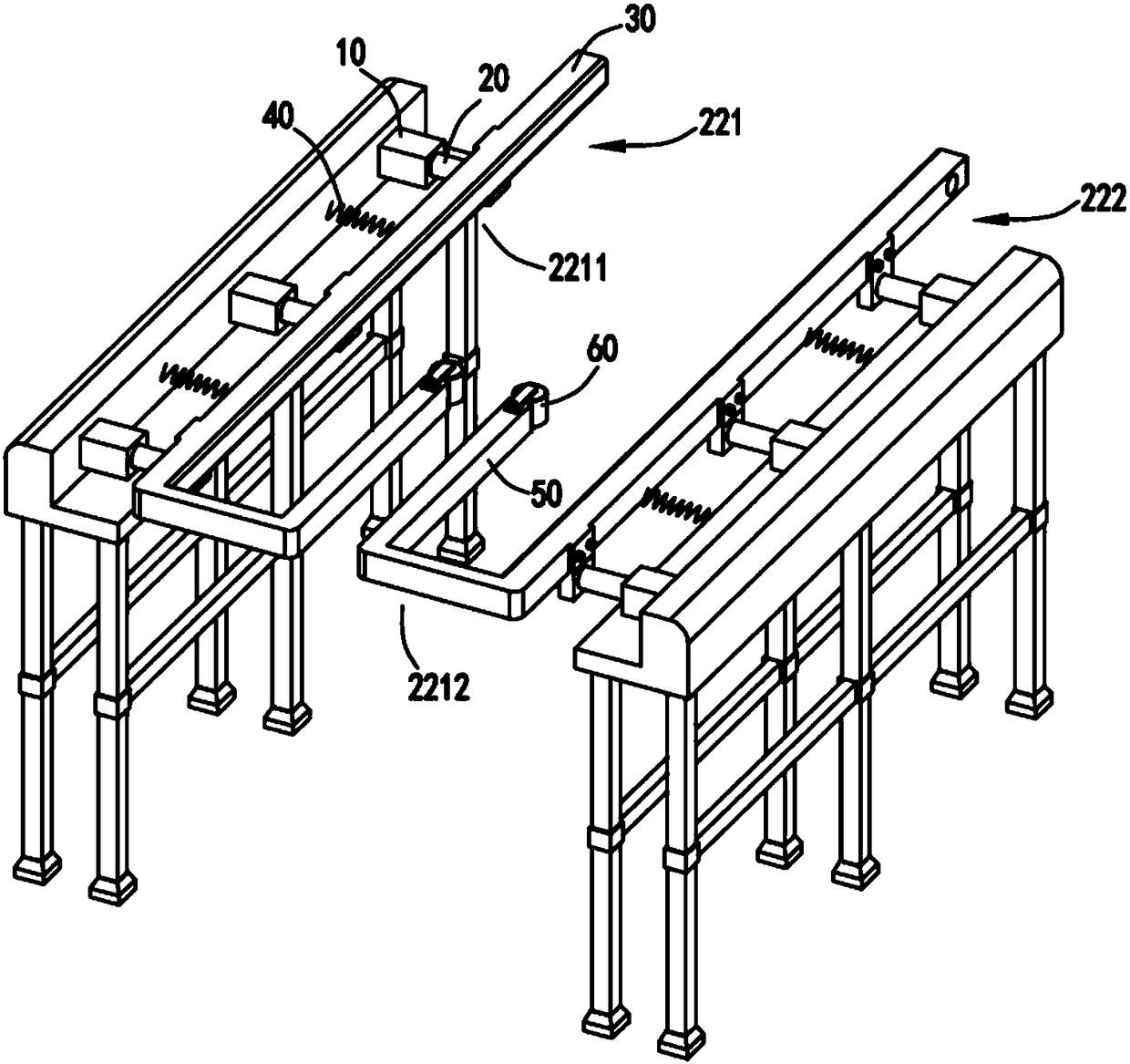
[0045] The fixed part 2, the fixed part 2 includes a fixed frame 21 and a clamping device 22 installed on the fixed frame 21, the clamping device 22 is used to communicate with the carrying device when the moving part 1 transfers the patient to the fixed part 2 12 cooperate to support and fix the bed body 14;

[0046] The disconnecting device 13 is used to control the quick disconnection between the bed 14 and the walking frame 11 or the clamping device 22.

[0047] It is worth mentioning that by changing ...

Embodiment 2

[0063] Such as figure 1 , figure 2 , image 3 , Figure 4 , Figure 5 , Image 6 , Figure 7 , Figure 8 , Picture 9 with Picture 10 As shown, the components that are the same as or corresponding to those in the first embodiment adopt the reference numerals corresponding to those in the first embodiment. For simplicity, only the differences from the first embodiment are described below. The second embodiment is different from the first embodiment in that: further, the two ends of the front side of the walking frame 11 are also provided with positioning components 4, and correspondingly, the supporting member a121 and the supporting member b122 are close to the supporting member 123. A positioning rod 5 is provided at the bottom of one end,

[0064] The positioning assembly 4 includes positioning grooves 41 opened at both ends of the front side of the walking frame 11 and matched with the positioning rods 5, and a guide block a42 and a guide block b43 arranged outside the posit...


PUM


Abstract

The invention relates to a combined sickbed for patient operation transfer. The combined sickbed comprises a mobile part and a fixing part, wherein the mobile part is used for transferring a patient,and comprises a walking shelf, a bed body installed on the walking shelf, a bearing device arranged below the bed body and a disconnecting device arranged at one side of the bearing device, the fixingpart comprises a fixing shelf and a clamping device installed on the fixing shelf, the clamping device is used for cooperating with the beating device when the mobile part transfers the patient to the fixing part to support and fix the bed body, the disconnecting device is used for controlling the bed body and the walking shelf or the clamping device to be quickly disconnected. By means of the combined sickbed for the patient operation transfer, the problems are solved that much time is consumed in the process of transferring the patient, and secondary injury to the patient is easily caused when the patient needs to be transferred to another bed from one bed in the transferring process.

Description

Technical field [0001] The invention relates to the technical field of hospital bed equipment, in particular to a combined hospital bed for patient operation transfer. Background technique [0002] The rescue bed is used to quickly transfer the patient to be treated. The patient races against time in the rescue process. For example, when the patient is transferred from the ambulance to the operation bed, the patient needs to be moved from the rescue bed to the operation bed. After the operation is completed It is more troublesome and wastes rescue time to move the patient from the surgical bed to another bed. [0003] A Chinese invention patent with application number 201710132101.8 discloses a hospital bed, including a mother bed and a child bed, by setting a side guide wheel group and a bottom guide wheel group at both ends of the mother bed frame, a side guide wheel group and a bottom guide wheel The two ends of the sub-bed frame are respectively installed in the guiding channe...

Claims


Application Information

Patent Timeline
IPC IPC(8): A61G13/08A61G13/10A61G1/02
Inventor 胡玉琴
Owner HUZHOU CENT HOSPITAL
Learn More