
Pollutant collecting-and-discharging system for pond internal-circulation aquaculture

A sewage system and internal circulation technology, applied in fish farming, application, animal husbandry, etc., can solve the problems of heavy equipment maintenance workload, unfavorable environmental sanitation, difficult management, etc., and prevent the content of ammonia nitrogen and other harmful substances from rising. , Improve the effect of sedimentation and collection, and the effect of harmonizing emissions

Pending Publication Date: 2018-06-26
HUBEI SHUIZHIYI TECH CO LTD
View PDF11 Cites 3 Cited by
  • Summary
  • Abstract
  • Description
  • Claims
  • Application Information

AI Technical Summary

Problems solved by technology

The outlet of the sewage suction pump moves with the pump body, and the sewage discharge tank can only be set as an open type, which is not conducive to environmental sanitation
Large-scale farms have many breeding tanks and must be equipped with multiple sewage suction pumps. The investment is large, the management is difficult, and the equipment maintenance workload is heavy.

Method used


Image

  • Pollutant collecting-and-discharging system for pond internal-circulation aquaculture
  • Pollutant collecting-and-discharging system for pond internal-circulation aquaculture
  • Pollutant collecting-and-discharging system for pond internal-circulation aquaculture

Examples


Embodiment Construction

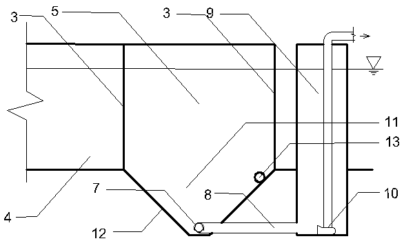
[0023] The present invention will be described below in conjunction with the accompanying drawings. figure 1 It is the arrangement mode of the prior art. attached figure 2 It is the layout diagram of the basic scheme of the present invention. Compared figure 1 and figure 2It can be seen that the improvement of the present invention to the prior art is: the bottom of the sewage collection area 5 immediately behind the breeding area 4 is a trapezoidal sewage collection tank 11 with a large upper part and a smaller one at the lower part, and a turbidity monitoring is set at the outlet side of the sewage collection tank 11 Instrument 13, sewage collection area 5 outlet side heights are consistent with breeding area 4 bottom surface heights, sewage collection tank 11 bottoms are provided with perforated sewage pipe 7, and perforated sewage pipe 7 is closed at one end, and the other end access sewage pipe. When the number of aquaculture tanks is large, it should be arranged in...


PUM


Abstract

The invention relates to a pollutant collecting-and-discharging system for pond internal-circulation aquaculture. The pollutant collecting-and-discharging system comprises a big-end-up trapezoidal pollutant collecting groove (11) formed in the portion, close to the back portion of a breeding area (4), in the bottom of a pollutant collecting area (5), a turbidity monitor (13) is arranged at the portion, close to an outlet side of the pollutant collecting area (5), of the pollutant collecting groove (11), and the height of the water outlet side of the pollutant collecting area (5) is coincidentwith the height of the bottom face of the breeding area (4); a punching pollutant discharging pipe (7) is arranged at the bottom of the pollutant collecting groove (11), one end of the punching pollutant discharging pipe (7) is closed, and the other end of the punching pollutant discharging pipe (7) is connected into a pollutant discharging pipe (8); pollutants in a breeding water body are precipitated in the pollutant collecting groove (11) and discharged through the punching pollutant discharging pipe (7) and the pollutant discharging pipe (8). Construction is easy, movable equipment is notarranged, the sedimentation effect of fish manure and residual feed can be enhanced, residence time of the fish manure in the breeding water body is shortened, real-time monitoring is carried out through the turbidity monitor (13), collecting and discharging efficiency of the pollutant are improved, cleaning of the breeding water body is guaranteed, and the management difficulty and the working amount of equipment maintenance are effectively reduced.

Description

technical field [0001] The invention relates to the technical field of aquaculture, in particular to a sewage collection and discharge system for circulating aquaculture in ponds. Background technique [0002] Recirculating aquaculture technology in ponds has been introduced from abroad in recent years. Because its economic benefits and environmental ecological benefits have been significantly improved compared with traditional aquaculture models, it has been promoted very quickly in China. [0003] figure 1 It is a vertical section view of the main part of the existing pond recirculating aquaculture mode that has been implemented in many places. The fish pond is separated by a side wall 1, and several aquaculture tanks with a total length of about 27 meters and a width of about 5 meters are formed in the pond. The area of ​​the breeding tank accounts for about 3% to 5% of the total area of ​​the large pond. The water flow in the big pond passes through the airlift pushing...

Claims


Application Information

Patent Timeline
IPC IPC(8): A01K63/04
CPCA01K63/04
Inventor 刘奎张家柱吴宝霞左小强刘哲
Owner HUBEI SHUIZHIYI TECH CO LTD
Learn More