
A verification method and system for a robot joint communication system model

A technology of robot joints and communication systems, applied in the field of verification of robot joint communication system models, can solve problems such as limited parameter settings, dependence on hardware, and inaccurate test results, and achieve the goal of reducing arbitration delay and increasing node load Effect

Active Publication Date: 2021-07-20
CAPITAL NORMAL UNIVERSITY
View PDF5 Cites 0 Cited by
  • Summary
  • Abstract
  • Description
  • Claims
  • Application Information

AI Technical Summary

Problems solved by technology

[0003] In the CAN bus protocol specification, the static priority strategy of information is used for communication, which can basically guarantee real-time performance. However, with the increase of nodes on the CAN bus and the improvement of real-time requirements, the static priority strategy cannot meet the delay requirements of transmission between nodes.
[0004] At present, the verification of CAN bus protocol is mainly concentrated in the control system of electric vehicles. In these verification methods of CAN protocol, traditional testing, simulation and simulation methods are mainly used. However, these three methods have certain limitations. It cannot cover all execution paths, so it will lead to incomplete verification results
The traditional test method is to use a physical machine to build a test platform for parameter setting and testing in the final stage of design. This method needs to be carried out in the final stage, and the parameter setting during the test process is limited, resulting in inaccurate test results.
The traditional simulation and emulation methods mainly use computer software for environment simulation and action simulation, and then for communication analysis. However, this method relies on hardware and provides limited parameter settings, which will also lead to incomplete verification results.

Method used


Image

  • A verification method and system for a robot joint communication system model
  • A verification method and system for a robot joint communication system model
  • A verification method and system for a robot joint communication system model

Examples


Embodiment Construction

[0047] The specific implementation manners of the present invention will be described in detail below in conjunction with the accompanying drawings.

[0048] In order to make the purpose, technical solutions and advantages of the embodiments of the present invention clearer, the technical solutions in the embodiments of the present invention will be clearly and completely described below in conjunction with the drawings in the embodiments of the present invention. Obviously, the described embodiments It is a part of embodiments of the present invention, but not all embodiments. Based on the embodiments of the present invention, all other embodiments obtained by persons of ordinary skill in the art without making creative efforts belong to the protection scope of the present invention.

[0049] In robot communication, the tasks of service robots have concurrency and high real-time requirements. Therefore, how to design the model according to the bus protocol specifications and ...


PUM


Abstract

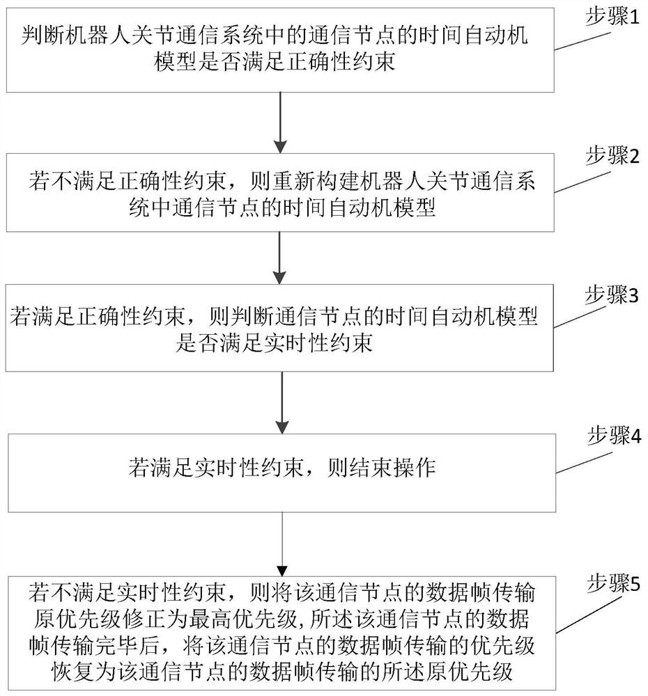
The present invention relates to a verification method and system for a model of a robot joint communication system. The method includes: adopting a formal method to model and analyze a control system based on a CAN field bus, in which the model needs to be abstracted for the system, and then formally constructed. Modeling and verification, judging whether the time automaton meets the correctness and real-time performance, if the correctness is not satisfied, the system plan is re-planned, if the real-time performance is not satisfied, the real-time performance is improved by deploying a dynamic priority strategy, the technology provided by the present invention The scheme uses a formal description to establish a timed automaton model and verifies the correctness and real-time performance of the timed automaton in the UPPAAL tool. If the real-time constraints are not met, a dynamic priority strategy is deployed.

Description

technical field [0001] The invention relates to the field of robot communication, in particular to a verification method and system for a robot joint communication system model. Background technique [0002] Robot applications are becoming more and more extensive, not limited to industry. Due to market demand, a large number of service robots have begun to be used in medical care and households. Due to the complexity, high concurrency, and high requirements for real-time performance of the robot communication system, it is very important to ensure that the robot completes the expected action accurately and in real time, especially in the information transmission between the distributed nodes of the robot, the communication delay must meet Specify the requirements for response time, otherwise it will affect the stability of the system or cause system errors and crashes. [0003] In the CAN bus protocol specification, the static priority strategy of information is used for co...

Claims


Application Information

Patent Timeline
Patent Type & Authority Patents(China)
IPC IPC(8): H04L12/40H04L12/26H04L12/24
CPCH04L12/4015H04L41/145H04L43/16H04L43/50H04L2012/40215
Inventor 李晓娟关永孟瑶王瑞施智平张倩颖谈金东邵振洲张杰王国辉刘永梅吴敏华
Owner CAPITAL NORMAL UNIVERSITY
Learn More