Rotor vertical fixing device and rotor vertical fixing method

A fixing method and a technology of a fixing device, which are applied in the direction of adjusting/balancing the rotor, etc., can solve problems such as easily damaged bearing inner rings and bearing stop fitting surfaces, affecting bearing assembly quality, scrapping of bearings and rotating shafts, etc., and achieve simple structure and improved Reliability and accuracy, efficiency-enhancing effects

Active Publication Date: 2019-10-29
CSR ZHUZHOU ELECTRIC CO LTD
View PDF4 Cites 0 Cited by
  • Summary
  • Abstract
  • Description
  • Claims
  • Application Information

AI Technical Summary

Problems solved by technology

[0002] Due to the narrow space of the tram bogie, the low-floor traction motor has a special slender structure, the inner ring of the non-end ball bearing and the shaft are interference fit, and the outer side of the non-end bearing is fastened with a round nut. The overall press-fitting of the non-end ball bearing and the end cover of the subway traction motor is to press-fit the non-end ball bearing and the end cover to the rotor horizontally with the aid of a hydraulic pull rod and other devices. This method has the following disadvantages: cold press assembly It is only suitable for the fit method with small interference. For the fit method with large interference, it is very easy to damage the inner ring of the bearing and the fitting surface of the bearing stopper during cold pressing, which will affect the quality of bearing assembly. manufacturing cost
The fixture structure in the above scheme is complicated, and it can only be adapted to the vertical clamping of a rotor with a shaft length, which has poor versatility, and the direction accuracy of the vertical rotor needs to be improved.

Method used


Image

  • Rotor vertical fixing device and rotor vertical fixing method
  • Rotor vertical fixing device and rotor vertical fixing method
  • Rotor vertical fixing device and rotor vertical fixing method

Examples


Embodiment Construction

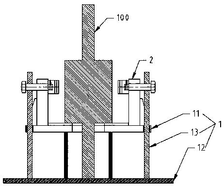
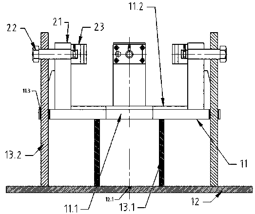
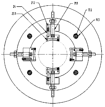
[0030] Attached below Figure 1~3 Embodiments of the present invention are described in detail.

[0031] The rotor vertical fixing device includes a support table 1 and a clamping assembly 2 arranged on the support table 1. The rotor 100 stands on the support table 1, and the clamping assembly 2 clamps the rotor 100. It is characterized in that the support table 1 includes an upper support plate 11 for supporting the weight of the rotor 100, a bottom plate 12 located directly below the upper support plate 11 and having a larger area than the upper support plate 11, and a support adjustment assembly 13 that can drive the upper support plate 11 to move up and down, the support adjustment assembly 13 Fixed on the base plate 12 to support the upper support plate 11, the center of the upper support plate 11 has a through hole 11.1 with a diameter smaller than the maximum diameter of the rotor 100, the rotating shaft of the rotor 100 passes through the through hole 11.1, and the end...


PUM


Abstract

Provided is a vertical fixing device for a rotor. The device includes a support table and a clamping assembly arranged on the support table, the rotor is vertically placed on the support table, the clamping assembly clamps the rotor, the device is characterized in that the support table includes an upper support plate for supporting the weight of the rotor, a bottom plate which is positioned underthe upper support plate and is larger than the upper support plate, and a support adjustment assembly capable of driving the upper support plate to move up and down, the support adjustment assembly is fixed on the bottom plate and used for supporting the upper support plate, a through hole with the diameter smaller than the maximum diameter of the rotor is formed in the center of the upper support plate, a rotating shaft of the rotor penetrates the through hole, the end face of the rotating shaft is in contact with the center of the bottom plate, and the upper support plate is provided with arubber gasket in contact with the rotor. The device is used for vertically fixing the rotor and is simple in structure and high in universality, the vertical placing direction of the rotor is high inprecision, and the reliability and accuracy of vertical processing of the rotor are improved. The invention further provides a vertical fixing method for the rotor.

Description

technical field [0001] The invention relates to a rotor vertical fixing device and a rotor vertical fixing device, which are used for vertical fixing of the rotor and belong to the technical field of motor manufacturing. The invention also relates to a vertical fixing method for the rotor. Background technique [0002] Due to the narrow space of the tram bogie, the low-floor traction motor has a special slender structure, the inner ring of the non-end ball bearing and the shaft are interference fit, and the outer side of the non-end bearing is fastened with a round nut. The overall press-fitting of the non-end ball bearing and the end cover of the subway traction motor is to press-fit the non-end ball bearing and the end cover to the rotor horizontally with the aid of a hydraulic pull rod and other devices. This method has the following disadvantages: cold press assembly It is only suitable for the fit method with small interference. For the fit method with large interferen...

Claims


Application Information

Patent Timeline
Patent Type & Authority Patents(China)
IPC IPC(8): H02K15/16
CPCH02K15/16
Inventor 夏红勇杨下沙刘权熊文浩龙云峰王梓林何锋杰赵俊程郭琳琳邓先平龙宇涛曹家熙王靖博
Owner CSR ZHUZHOU ELECTRIC CO LTD
Why Eureka
Try Eureka