A lithium battery winding device and winding process

A technology of winding device and pressurizing device, which is applied in the direction of secondary batteries, circuits, electrical components, etc., can solve the problems of increasing manufacturing costs, scrapping, short-circuiting diaphragms, etc., and achieve the goal of improving product rate performance, reducing costs, and reducing difficulty Effect

Active Publication Date: 2020-04-07
ZHEJIANG FOREVER NEW ENERGY TECH CO LTD +1
View PDF5 Cites 0 Cited by
  • Summary
  • Abstract
  • Description
  • Claims
  • Application Information

AI Technical Summary

Problems solved by technology

like figure 1 and figure 2 As shown, since the positive electrode sheet, the negative electrode sheet, and the separator are separated from each other, during the winding process of the existing winding process, the positive electrode roll 11, the separator roll 12, the negative electrode sheet roll 13 and the separator roll in the separated state 12 is simultaneously transported to the winding mechanism 3 by the unwinding mechanism 1 and the roller passing mechanism 2 for winding. The existing winding process is not easy to control the separated positive electrode sheet, separator and negative electrode sheet, and it is prone to deflection. In addition, the air bubbles between the positive electrode sheet and the separator and the negative electrode sheet and the separator are not easy to discharge, resulting in short circuit, size and other defects. On the one hand, the production efficiency will be reduced, on the other hand, it will also be scrapped and increase the manufacturing cost.
In addition, the existing winding process is mainly applied to battery products with hard shells (such as aluminum shells, steel shells, plastic shells, etc.), therefore, the existing winding process has certain limitations in the entire industry
[0004] see image 3 , image 3 It is a flow chart of the manufacturing process of lithium battery stacks in the prior art, such as image 3 As shown, since the positive electrode, separator, and negative electrode are separated from each other, the existing lamination process is to grab the electrode from the positive / negative electrode box and place it on the separator through the interval of the manipulator. The lamination process needs precise control Lamination size, and the existing lamination method has the following defects in the process of stacking: (1) The positive electrode sheet, separator and negative electrode sheet are in a separated state, and no adhesion is formed, and the upper and lower layers are prone to Misalignment, resulting in abnormalities such as short circuit or diaphragm folds; (2) The hardness of the battery cells made by the existing lamination method cannot meet the requirements, which leads to the difficulty of inserting the battery cells into the shell during assembly; (3) The existing The stacking method, air enters between the positive electrode sheet and the separator and the negative electrode sheet and the separator, and the air bubbles in the product are not easy to discharge during the subsequent exhaust, which increases the complexity of the process and also increases the production cost.
At present, the stacking or stacking process in the industry is mainly used in the production of soft-pack lithium batteries. Due to the special structure of soft-pack batteries, no subsequent winding process is required after the positive electrode sheet, separator and negative electrode sheet are stacked. Therefore, the existing The lamination or lamination process has certain limitations throughout the industry
[0005] In addition, since the positive electrode sheet, the separator and the negative electrode sheet are separated from each other, after the hard-shell battery or the soft-pack battery is wound or stacked using the above-mentioned existing winding process or lamination process, the positive electrode sheet, the separator, and the negative electrode The bonding effect between the sheet and the separator is poor, and the transmission channel of lithium ions is lengthened during the charging and discharging process of the finished battery, resulting in poor charging and discharging effect

Method used


Image

  • A lithium battery winding device and winding process
  • A lithium battery winding device and winding process
  • A lithium battery winding device and winding process

Examples


Embodiment 1

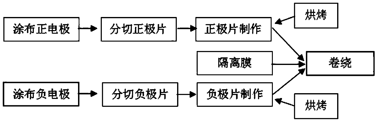
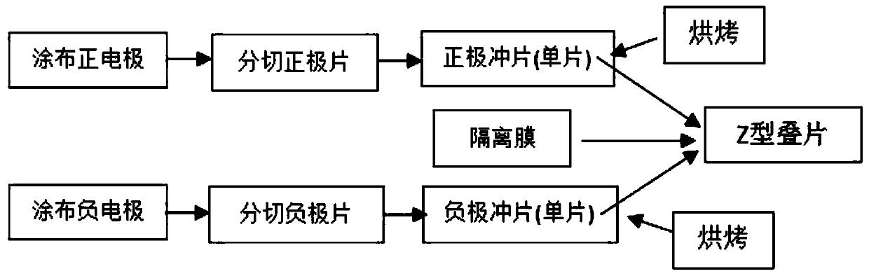
[0055] see Figure 4 , Figure 4 It is a flow chart of the winding process of the present invention. Such as Figure 4 As shown, the production process of the positive electrode sheet is: coating the positive electrode, cutting the positive electrode sheet, making and baking the positive electrode sheet; the production process of the negative electrode sheet is: coating the negative electrode sheet, cutting the negative electrode sheet, making and baking the negative electrode sheet , the baked positive electrode sheet, the separator and the baked negative electrode sheet are laminated and then wound.

[0056] The present invention improves the process by changing the current conventional winding method. After the positive / negative electrode sheet is made and baked, the positive / negative electrode sheet is laminated on the separator before winding, and then transported to the winding mechanism. for winding.

[0057] see Figure 5 , Figure 5 It is the winding schematic d...

Embodiment 2

[0069] see Figure 5 , Figure 5 It is the winding schematic diagram of the winding process of the present invention. Such as Figure 5 As shown, the winding device of the present invention includes an unwinding mechanism 100 , a roller passing mechanism 200 , a stacking mechanism 300 and a winding mechanism 400 .

[0070] The unwinding mechanism 100 is used to unwind the positive electrode sheet 1021 , the separator 1031 and the negative electrode sheet 1041 respectively, wherein the positive electrode sheet 1021 , the separator 1031 and the negative electrode sheet 1041 are independently wound on the unwinding mechanism. In this embodiment, the positive electrode sheet 1021, the separator 1031 and the negative electrode sheet 1041 are independently wound on the unwinding mechanism. It does not mean that there is only one layer of separator, but that the separators are alternately arranged on the positive electrode sheet and the negative electrode sheet. Between the negati...

Embodiment 3

[0079] The difference from Embodiments 1 and 2 is that in this embodiment, the upper and lower surfaces of the laminated positive electrode sheet, separator, negative electrode sheet, and separator are covered with PET protective films, respectively. read on Figure 5 , the PET protective film 1011 is wound into a PET protective film roll 101 on the unwinding mechanism 100 . The PET protective film roll 101 , the positive pole roll 102 , the separator roll 103 , the negative pole roll 104 , the separator roll 103 and the PET protective film roll 101 are sequentially arranged on the unwinding mechanism from top to bottom. The PET protective film roll 101 , positive electrode roll 102 , separator roll 103 , negative electrode roll 104 , separator roll 103 and PET protective film roll 101 are unwound simultaneously.

[0080] A pair of pressing rollers 309 and a PET protective film winding mechanism 305 arranged outside the pressing rollers 309 are arranged at the output port of ...


PUM


Abstract

The invention provides a lithium battery winding device and a winding process. The winding device includes an unwinding mechanism, a roller passing mechanism and a winding mechanism. The winding device also includes a lamination and lamination mechanism. The unwinding The mechanism is used to unwind the positive electrode sheet, separator and negative electrode sheet at the same time, and the roller passing mechanism is used to transport the positive electrode sheet, separator and negative electrode sheet from the unwinding mechanism to the lamination lamination mechanism; the lamination lamination The mechanism is used to sequentially stack and laminate the positive electrode sheet, separator and negative electrode sheet; the winding mechanism is used to wind the laminated positive electrode sheet, separator and negative electrode sheet. The invention avoids adjusting the position of the positive / negative electrode sheet and the separator in the winding mechanism by laminating the position of the positive / negative electrode sheet and the separator, and can shorten the transmission channel of lithium ions in the working process of the finished battery , so as to improve the product rate performance, reduce internal resistance and other performance.

Description

technical field [0001] The invention relates to the field of lithium batteries, in particular to a lithium battery winding device and a winding process. Background technique [0002] With the development of lithium-ion batteries, its process technology has also been continuously optimized and improved. At present, the manufacture of lithium-ion batteries (including power batteries and 3C product lithium batteries) is mainly divided into winding process and lamination process from the perspective of process differences. The winding process is mainly used in 3C target products lithium-ion batteries and square aluminum case power batteries; the lamination process is mainly used in soft pack power batteries. [0003] see figure 1 and figure 2 , figure 1 For the existing lithium battery winding manufacturing process flow chart, figure 2 It is the winding principle diagram of the existing winding manufacturing process. During the winding process of lithium-ion batteries, i...

Claims


Application Information

Patent Timeline
Patent Type & Authority Patents(China)
IPC IPC(8): H01M10/0587
CPCH01M10/0587Y02E60/10Y02P70/50
Inventor 吴赛舟孙晓辉马国
Owner ZHEJIANG FOREVER NEW ENERGY TECH CO LTD
Why Eureka
Try Eureka