
Cell smear dyeing machine structure

A cell smear and dyeing machine technology, applied in the field of instruments and equipment, can solve the problems of inability to withstand multi-task and multi-batch co-dyeing requirements, inability to make the best use of materials, and no anti-corrosion function, so as to achieve multi-functionality and prevent liquid Interference, strong heat dissipation effect

Active Publication Date: 2018-06-22
HEER MEDICAL TECH DEV CO LTD
View PDF6 Cites 5 Cited by
  • Summary
  • Abstract
  • Description
  • Claims
  • Application Information

AI Technical Summary

Problems solved by technology

[0004] (1) Poor practicability
At present, most of the automatic staining machines on the market are designed for large-scale staining, and can show their effectiveness in processing a large number of specimen slides. Using this kind of staining machine for small-batch staining will cause more equipment to be idle, so spend a lot of money to buy Into the automatic dyeing machine but can not make the best use of everything, resulting in waste
Although there are also some small dyeing machines that can be applied, their functions are relatively single, and they are developed and designed for special dyeing, and generally cannot withstand the needs of multi-task and multi-batch co-dyeing, lacking flexibility
[0005] (2) Large volume and weight
[0006] (3) No anti-corrosion function
So far, there is no dyeing machine that can adapt to such a highly corrosive environment. Dyeing like this can only be done manually in a fume hood

Method used


Image

  • Cell smear dyeing machine structure
  • Cell smear dyeing machine structure
  • Cell smear dyeing machine structure

Examples


Embodiment Construction

[0038] The following examples are presented to illustrate certain embodiments of the invention and should not be construed as limiting the scope of the invention. The content disclosed in the present invention can be improved simultaneously from materials, methods and reaction conditions, and all these improvements should fall within the spirit and scope of the present invention.

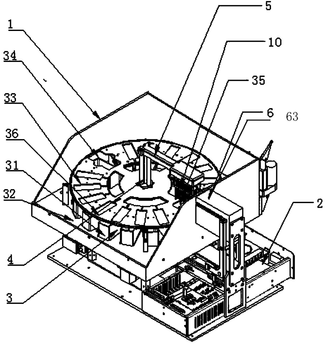
[0039] combine figure 1 and figure 2 , a cell smear staining machine structure, which includes a housing 1, a control module 2 and a core working module 3, the control module 2 and the core working module are all arranged inside the housing 1, and the control module 2 is connected to the core working module;

[0040] Such as figure 1 As shown, the control module 2 includes a control box 21, a control box UPS power supply 22, a display screen 23 and a junction box 24. The control box 24 is used for monitoring information and controlling movement, and is the core component of the control. card, po...


PUM


Abstract

The invention discloses a cell smear dyeing machine structure. The structure comprises a casing, a control module and a core work module, wherein the control module and the core work module are arranged in the casing, and the control module is connected with the core work module. A dyeing machine is designed by focusing on low cost, small size, multiple functions and corrosion resistance, and thedesign of the core work module and the control module meets small-lot multi-batch co-dyeing demands; besides, the cell smear dyeing machine structure performs anti-corrosion protection on each structure of the core work module to prevent the core work module from being damaged. A fluid control module provides clear water required for cleaning and discharges waste liquids, a constant-temperature water bath module provides the constant-temperature demands of special dyeing vats, the temperature of dye liquor in the dyeing vats is controlled in a water bath manner, and an exhaust and lid openingfunction module is used for controlling auxiliary operations such as exhausting of waste gas, automatic opening and closing of a lid. Miniaturization and multiple functions of the dyeing machine are realized, and the service life of the device is notably prolonged.

Description

technical field [0001] The invention relates to an instrument and equipment for performing smear staining on cells for medical examination and biological research, in particular to a structure of a cell smear staining machine. Background technique [0002] Staining is the most important link in the production of biological microscope slide specimens. It is to use dyes to give colors to tissue sections, so that they can interact with certain components in tissues or cells. Its various microstructures can show different colors, so that various components of tissue cells can be displayed under the microscope. In today's medical diagnosis, stained cell specimens have been widely used by medical scientists and biopathologists to assist in the diagnosis of diseases. As a preparatory step for observing patient tissues under a microscope, the staining process of cell smears has been done by hand for a long time. However, manual dyeing is often difficult to control the dyeing time....

Claims


Application Information

Patent Timeline
Patent Type & Authority Applications(China)
IPC IPC(8): G01N1/31
CPCG01N1/31
Inventor 廖乘胜
Owner HEER MEDICAL TECH DEV CO LTD
Learn More