Non-combustible phase change thermal thruster
What is Al technical title?
Al technical title is built by PatSnap Al team. It summarizes the technical point description of the patent document.
A technology of phase-change heat and thrust devices, which is applied in the field of power engineering and can solve problems such as environmental pollution, long industrial production chains, and environmental pollution from gunpowder
Active Publication Date: 2020-10-23
西北机电工程研究所
View PDF4 Cites 0 Cited by
Summary
Abstract
Description
Claims
Application Information
AI Technical Summary
This helps you quickly interpret patents by identifying the three key elements:
Problems solved by technology
Method used
Benefits of technology
Problems solved by technology
[0002] The existing rocket propulsion technology is very mature and can carry out various human activities. However, compared with the diversified needs, its shortcomings are also obvious, such as complex technology, long industrial production chain, many special processes and special materials, and support tasks. Heavy, high cost, polluting the environment, when carrying out some special tasks, its economy is not enough, such as large-scale air mines, dealing with a large number of "low-altitude, small, slow" targets, large-scale artificial rainfall, and carrying out large-scale throwing tasks at low altitudes (such as metal foil), deploying aerial reconnaissance equipment, etc.
[0003] Due to the extensive use of dry ice in the existing artificial rainfall technology, the vaporized carbon dioxide is unfavorable to the atmospheric environment (the greenhouse effect is enhanced), and the gunpowder used in the launch causes serious pollution to the environment
Method used
Image
Click on the blue label to locate the original text in one second.
Reading with bidirectional positioning of images and text.
Examples
Embodiment
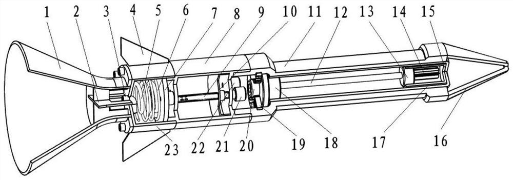
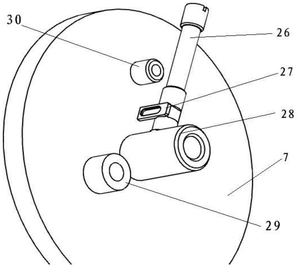
[0045] Such as Figure 1 to Figure 6 As shown, this embodiment includes a nozzle 1, a deflector 2, a spout 3, a tail rudder 4, a spiral tube 5, an electric heating tube 6, a plugging cover 7, a cold cabin 8, a liquid injection pipe 9, a piston 10, and a load cabin 11 , detonator 12, timing device 13, explosive 14, storage cylinder 15, head cover 16, profile 17, tail block 18, retaining ring 19, first screw plug 20, second screw plug 21, third screw plug 22, heat Cabin 23, throttle valve 25, throttle rod 26, reed 27, outlet pipe 28, nozzle 29, electric heating joint 30, sealing ring 31, liquid outlet 32; Figure 4 The feature A of the middle throttle rod is the throttle port A, the feature B is the positioning ring B, and the feature C is the open groove C.
[0046] The nozzle 1 and the hot cabin 23 are connected by anti-loosening screws, the deflector 2 is fixedly connected with the nozzle 1; The load compartment 11 is fixedly connected, and the load compartment 11 is fixedl...
PUM
Abstract
The invention belongs to the technical field of power engineering and particularly relates to a non-combustion-type phase-change heat transfer thrust device. The non-combustion-type phase-change heattransfer thrust device comprises a spray tube, a flow guiding plate, a spray opening, a tail vane, a spiral tube, an electrical heated tube, a blanking cover, a cold chamber, a liquid injection tube,a piston, a loading cabin, a detonator, a timing device, an explosive, a storage tube, a hood, a sectional material, a tail block, a check ring, a first plug, a second plug, a third plug, a hot cabin,a throttling valve, a throttling rod, a reed, an outlet tube, a nozzle, an electrical heated connector, a sealing ring and a liquid outlet. Compared with the prior art, the non-combustion-type phase-change heat transfer thrust device has the following beneficial effects that (1) the technical integration is simple, and developing and guaranteeing tasks are easy; (2) the cost is low, and the economical efficiency is outstanding during large-scale use; and (3) environmental pollution is avoided, and the green concept is embodied in all links of manufacturing, adjustment and use.
Description
technical field [0001] The invention belongs to the technical field of power engineering, and in particular relates to a non-combustible phase-change thermal thrust device. Background technique [0002] The existing rocket propulsion technology is very mature and can carry out various human activities. However, compared with the diverse needs, its shortcomings are also obvious, such as complex technology, long industrial production chain, many special processes and special materials, and support missions. Heavy, high cost, pollutes the environment, and it is not economical when performing some special tasks, such as large-scale air mines, dealing with a large number of "low-altitude, small, slow" targets, large-scale artificial rainfall, and carrying out large-scale throwing tasks at low altitudes (such as metal foil), deploying aerial reconnaissance equipment, etc. [0003] Due to the extensive use of dry ice in the existing artificial rainfall technology, the vaporized ca...
Claims
Application Information
Patent Timeline
Application Date:The date an application was filed.
Publication Date:The date a patent or application was officially published.
First Publication Date:The earliest publication date of a patent with the same application number.
Issue Date:Publication date of the patent grant document.
PCT Entry Date:The Entry date of PCT National Phase.
Estimated Expiry Date:The statutory expiry date of a patent right according to the Patent Law, and it is the longest term of protection that the patent right can achieve without the termination of the patent right due to other reasons(Term extension factor has been taken into account ).
Invalid Date:Actual expiry date is based on effective date or publication date of legal transaction data of invalid patent.