
Ventilating and pumping device for crankcase

A crankcase ventilation and crankcase technology, which is applied to crankcase ventilation, charging system, adding non-fuel substances to fuel, etc., can solve problems such as air flow rate affecting the opening angle of the throttle valve, low oil replacement efficiency, and no cleaning effect. , to achieve the effect of improving oil replacement efficiency, good atomization effect and reducing labor intensity

Active Publication Date: 2018-06-22
JIANGSU UNIVERSITY OF TECHNOLOGY
View PDF9 Cites 0 Cited by
  • Summary
  • Abstract
  • Description
  • Claims
  • Application Information

AI Technical Summary

Problems solved by technology

However, the direct injection engine does not have the above-mentioned cleaning effect of gasoline on the throttle valve or the oil on the intake pipe, so that the oil droplets are deposited on the throttle valve or the inner wall of the intake pipe for a long time and form carbon deposits, so the direct injection engine is easier than the naturally aspirated engine. Carbon deposits are formed on the inner wall of the throttle valve and the intake pipe, which in turn affects the opening angle of the throttle valve and the air flow rate in the intake pipe
In addition, the oil in the crankcase is usually replaced manually, which is labor-intensive and the oil replacement efficiency is low

Method used


Image

  • Ventilating and pumping device for crankcase
  • Ventilating and pumping device for crankcase
  • Ventilating and pumping device for crankcase

Examples


Embodiment Construction

[0022] The present invention will be further described below in conjunction with the accompanying drawings and embodiments.

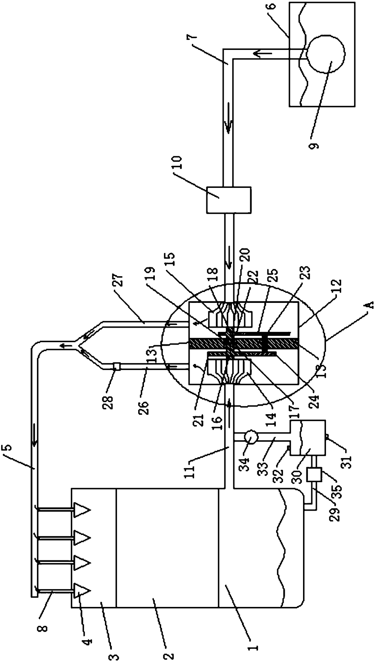
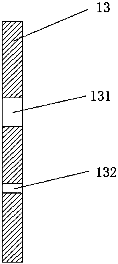
[0023] This embodiment proposes a crankcase ventilation and pumping device, such as figure 1 , 2 , 3, it includes crankcase 1, cylinder block 2, cylinder head 3, fuel injector 4, high-pressure fuel rail 5, fuel tank 6 and fuel delivery pipe 7, and high-pressure fuel rail 5 connects with corresponding cylinders through each connecting branch pipe 8 The fuel injector 4 is sealed and communicated. The fuel injector 4 is installed in the cylinder head 3, and its nozzle extends into the combustion chamber of the cylinder block 2. The cylinder head 3 is installed in the upper part of the cylinder block 2, and the lower part of the cylinder block 2 is installed There is a crankcase 1, the lower end of the oil delivery pipe 7 is in sealing communication with the outlet of the oil pump 9 in the fuel tank 6, the oil delivery pipe 7 is equipped with a pressurizin...


PUM


Abstract

The invention discloses a ventilating and pumping device for a crankcase, and belongs to the technical field of direction injection spark ignition engines. The ventilating and pumping device for the crankcase comprises the crankcase, a cylinder body, a cylinder cover, an oil injector, a high-pressure oil rail, an oil tank and an oil delivery pipe. A suction pipe is mounted on the side wall of thecrankcase and connected with an inlet of an air pump. An inner cavity of the air pump is divided into a left cavity and a right cavity by a partition plate. A left impeller is mounted in the left cavity, and a right impeller is mounted in the right cavity. The left impeller is fixedly connected with a first gear shaft. The first gear shaft rotates through a first bearing and is assembled at one inner end of a first through hole of the partition plate. The right impeller is fixedly connected with a second gear shaft. The second gear shaft rotates through a second bearing and is assembled at theother inner end of the first through hole of the partition plate. A sealing fin is mounted between the first gear shaft and the second gear shaft and used for isolating the left cavity from the rightcavity. By adoption of the ventilating and pumping device for the crankcase, the problems that carbon deposition happens to the inner walls of a throttle valve and an air inlet pipe of a direct injection engine, and engine oil in a crankcase needs to be changed manually are solved.

Description

technical field [0001] The invention belongs to the technical field of in-cylinder direct injection engines, in particular to a crankcase ventilation and pumping device. Background technique [0002] Nowadays, many automobile engines are in-cylinder direct-injection engines. Gasoline is directly injected into the cylinder for combustion. Although the power and torque of the engine at high speed are improved, it also brings some problems, such as the throttle valve and the wall of the intake pipe are easy to burn. Carbon deposits are produced. The cause of carbon deposition is mainly caused by the crankcase ventilation system of the engine. The crankcase ventilation system introduces a small amount of exhaust gas leaked into the crankcase into the intake pipe and mixes with the newly entered air into the cylinder to participate in combustion. A small amount of oil vapor enters the intake pipe together with the above-mentioned exhaust gas and passes through the throttle valve...

Claims


Application Information

Patent Timeline
IPC IPC(8): F01M13/02F02M25/06
CPCF01M13/021F01M2013/026F02M25/06
Inventor 汪伟贝绍轶汪永志陈卫兵杭卫星
Owner JIANGSU UNIVERSITY OF TECHNOLOGY
Learn More