
Pumping system and pumping machine

A pumping system and locking mechanism technology, which is applied in mechanical equipment, fluid pressure actuators, servo motor components, etc., can solve the problems of large inclination angle of the pumping system, unfavorable concrete suction, and restriction of the length of the delivery cylinder

Pending Publication Date: 2021-12-07
SANY AUTOMOBILE MFG CO LTD
View PDF0 Cites 0 Cited by
  • Summary
  • Abstract
  • Description
  • Claims
  • Application Information

AI Technical Summary

Problems solved by technology

[0003] However, the main oil cylinder of the existing pumping system is a single-stage oil cylinder, the concrete pumping volume is small, and the pumping efficiency is low
Moreover, the length of the main oil cylinder is too large in the length of the pumping system, which restricts the length of the delivery cylinder
At the same time, due to the constraints of the installation space of the chassis, the length of the main oil cylinder, and the length of the delivery cylinder, the inclination angle of the pumping system is too large, which is not conducive to the suction of concrete

Method used


Image

  • Pumping system and pumping machine
  • Pumping system and pumping machine
  • Pumping system and pumping machine

Examples


Embodiment Construction

[0038] In order to make the purpose, technical solutions and advantages of the present invention clearer, the technical solutions in the present invention will be clearly and completely described below in conjunction with the accompanying drawings in the present invention. Obviously, the described embodiments are part of the embodiments of the present invention , but not all examples. Based on the embodiments of the present invention, all other embodiments obtained by persons of ordinary skill in the art without creative efforts fall within the protection scope of the present invention.

[0039] Combine below Figure 1 to Figure 5 The pumping system of the present invention is described.

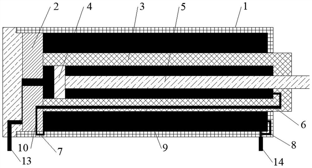
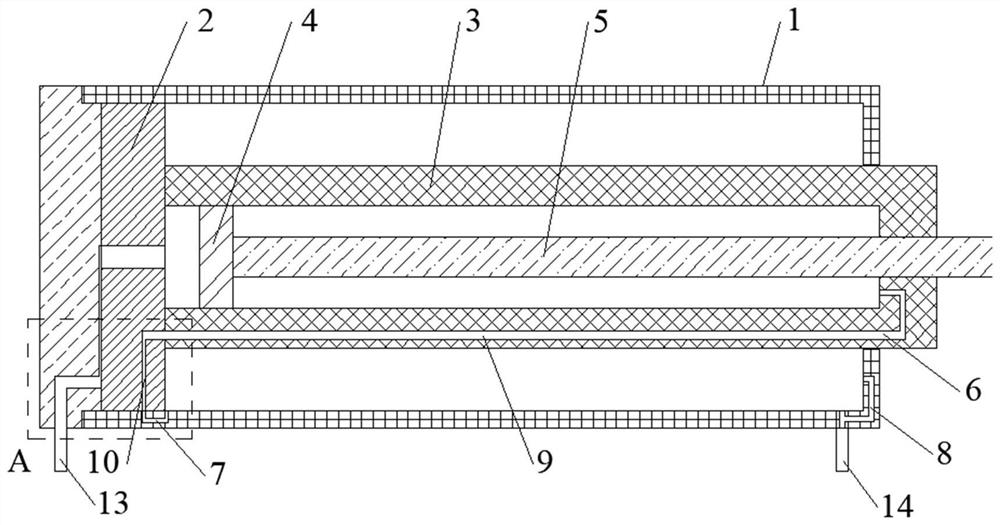
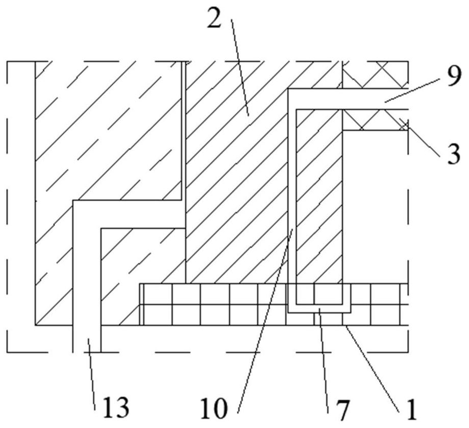
[0040] Such as Figure 1 to Figure 3 As shown, the embodiment of the present invention provides a pumping system, including a master cylinder 1 and a locking mechanism. Wherein, the main oil cylinder 1 includes a multi-stage oil cylinder embedded in the main oil cylinder 1 . In the multi...


PUM


Abstract

The invention provides a pumping system and a pumping machine. The pumping system comprises a main oil cylinder and a locking mechanism. Multiple stages of oil cylinders are embedded into the main oil cylinder, a piston rod of the previous stage of oil cylinder is a cylinder barrel of the next stage of oil cylinder, and a piston of the next stage of oil cylinder is located in a cylinder barrel of the previous stage of oil cylinder. Rodless cavities of all the stages of oil cylinders communicate with each other, and rod cavities of all the stages of oil cylinders communicate with each other. The locking mechanism is used for closing or opening the rod cavities of all the stages of oil cylinders to control the action sequence of the multiple stages of oil cylinders, and therefore the piston rods of all the stages of oil cylinders act in order, and stable and reliable operation of the system is guaranteed. In the one-time pumping process, when the piston rod of the previous stage of oil cylinder moves to the limit position, the piston rod of the next stage of oil cylinder starts to move, the concrete pumping amount is greatly increased, and the pumping efficiency is improved. The multiple stages of oil cylinders are arranged, and therefore the ratio of the length of the main oil cylinder to the length of the pumping system can be reduced, the space is reasonably utilized, the ratio of the length of a conveying cylinder to the length of the pumping system is increased, the inclination angle of the pumping system can also be reduced, and the material suction performance of the pumping system is improved.

Description

technical field [0001] The invention relates to the technical field of concrete pumping equipment, in particular to a pumping system and a pumping machine. Background technique [0002] The concrete pump truck is a machine that uses pressure to continuously transport concrete along the pipeline, and is composed of a pumping system and a pipeline. [0003] However, the main oil cylinder of the existing pumping system is a single-stage oil cylinder, the concrete pumping volume is small, and the pumping efficiency is low. Moreover, the length of the main oil cylinder accounts for too much in the length of the pumping system, which restricts the length of the delivery cylinder. At the same time, due to the constraints of the installation space of the chassis, the length of the main oil cylinder, and the length of the delivery cylinder, the inclination angle of the pumping system is too large, which is not conducive to the suction of concrete. Contents of the invention [000...

Claims


Application Information

Patent Timeline
IPC IPC(8): F15B15/16F15B15/14F15B15/26F15B13/02
CPCF15B15/16F15B15/1457F15B15/1428F15B15/1423F15B15/26F15B13/02
Inventor 万小龙邓习树钟琦
Owner SANY AUTOMOBILE MFG CO LTD
Learn More