
Thread trimming drive assembly, thread trimming mechanism and sewing machine

A technology for driving components and thread trimming, applied in the field of sewing machines, can solve the problems of complex parts structure, affecting assembly efficiency, and small installation space, and achieve the effects of simple parts structure, improved assembly production efficiency, and fewer parts number.

Active Publication Date: 2020-09-04
JACK SEWING MASCH CO LTD
View PDF5 Cites 0 Cited by
  • Summary
  • Abstract
  • Description
  • Claims
  • Application Information

AI Technical Summary

Problems solved by technology

In the existing implementation cases, the number of parts constituting the thread trimming drive assembly is large, the structure of the parts is relatively complex, the cost is high, and the installation space available for operation is small, which affects the assembly efficiency
Moreover, during the operation, since the action point of the sliding driving force of the thread trimming drive crank is not on the axis line of the thread trimming shaft, there is a risk of jamming during the driving process

Method used


Image

  • Thread trimming drive assembly, thread trimming mechanism and sewing machine
  • Thread trimming drive assembly, thread trimming mechanism and sewing machine
  • Thread trimming drive assembly, thread trimming mechanism and sewing machine

Examples


Embodiment Construction

[0061] The implementation of the present invention will be illustrated by specific specific examples below, and those skilled in the art can easily understand other advantages and effects of the present invention from the contents disclosed in this specification.

[0062] It should be noted that the structures, proportions, sizes, etc. shown in the drawings of this specification are only used to match the content disclosed in the specification, for those who are familiar with this technology to understand and read, and are not used to limit the implementation of the present invention. condition, so it has no technical substantive meaning, and any modification of structure, change of proportional relationship or adjustment of size shall still fall within the scope of the present invention without affecting the effect and purpose of the present invention. within the scope covered by the disclosed technical content. At the same time, terms such as "upper", "lower", "left", "right...


PUM


Abstract

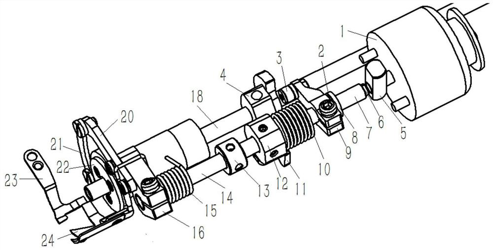
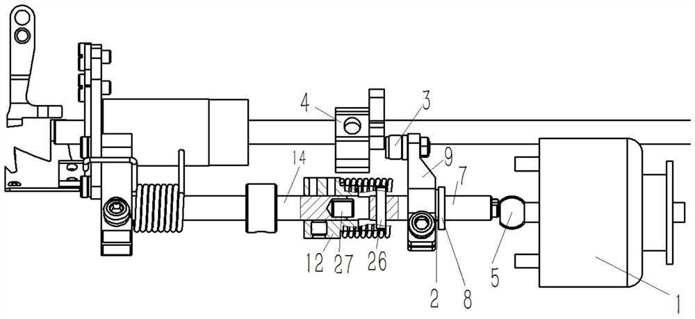
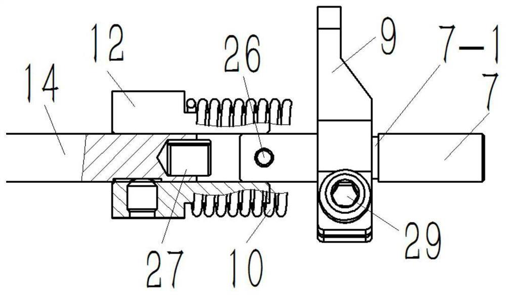
The invention relates to a thread shearing drive component, a thread shearing mechanism comprising the thread shearing drive component and a sewing machine comprising the thread shearing mechanism. The thread shearing drive component comprises a thread shearing shaft, a thread shearing drive crank, a drive shaft and drive cam and is characterized in that the thread shearing shaft comprises a thread shearing executing shaft and a torque transmission shaft, and the thread shearing drive crank is fixed on the torque transmission shaft; a fixed sleeve is fixed to the right end of the thread shearing executing shaft or the left end of the torque transmission shaft, the fixed sleeve is provided with an axial inner hole, and the left end of the torque transmission shaft or the right end of the thread shearing executing shaft can be slidably inserted into the axial inner hole; the torque transmission shaft or the thread shearing executing shaft is connected with the fixed sleeve through a slide connection structure. The thread shearing drive component and the thread shearing mechanism are few in parts, simple in part structure, convenient to mount, capable of effectively lowering production cost, capable of increasing assembling production efficiency and capable of greatly lowering the risk of getting stuck due to the fact that slide drive force can be allowed to act on the axis of thethread shearing shaft.

Description

technical field [0001] The invention relates to the technical field of sewing machines, in particular to a thread trimming drive assembly, a thread trimming mechanism including the thread trimming drive assembly and a sewing machine including the thread trimming mechanism. Background technique [0002] The thread trimming mechanism of the existing sewing machine usually needs to use the thread trimming drive assembly to transmit the torque of the drive shaft, such as the lower shaft of the sewing machine, to the thread trimming shaft. The wire cutter on the drive crank. In the existing implementation cases, the number of parts constituting the thread trimming drive assembly is large, the structure of the parts is relatively complex, the cost is high, and the installation space available for operation is small, which affects the assembly efficiency. Moreover, during the operation, since the action point of the sliding driving force of the thread trimmer driving crank is not ...

Claims


Application Information

Patent Timeline
Patent Type & Authority Patents(China)
IPC IPC(8): D05B65/00D05B69/00
CPCD05B65/00D05B69/00
Inventor 柯祥林祝书伟郑吉何明金
Owner JACK SEWING MASCH CO LTD
Learn More