
a vacuum device

A technology of vacuum device and vacuum pump, which is applied in the direction of vacuum evaporation plating, metal material coating process, coating, etc., which can solve the problems of chamber breaking vacuum, lower recovery efficiency, and affecting the operation effect of the whole machine, so as to achieve a simplified structure , Improve operation effect, easy repair and maintenance effect

Active Publication Date: 2020-06-09
SHENZHEN CHINA STAR OPTOELECTRONICS SEMICON DISPLAY TECH CO LTD
View PDF2 Cites 0 Cited by
  • Summary
  • Abstract
  • Description
  • Claims
  • Application Information

AI Technical Summary

Problems solved by technology

[0003] 1. The seal is installed on the inner wall of the chamber on both sides of the channel opening. When replacing it, the corresponding chamber needs to be vacuum-broken, which affects the operation effect of the whole machine; at the same time, the operator needs to work inside the chamber , the efficiency is low;
[0004] 2. When cleaning and maintaining a chamber with a sealed door, it is necessary to break the vacuum of the corresponding chamber at the same time, and the operator needs to work in a narrow space with a sealed door chamber, which is inefficient
[0005] 3. When the vacuum device is powered off or the CDA is cut off for a long time, the vacuum pump and the lifting cylinder cannot work, and the airtight door will open due to the falling of its own weight, causing the corresponding chamber to break the vacuum and reduce the recovery efficiency.

Method used


Image

  • a vacuum device
  • a vacuum device
  • a vacuum device

Examples


Embodiment Construction

[0024] The following will clearly and completely describe the technical solutions in the embodiments of the present invention with reference to the accompanying drawings in the embodiments of the present invention. Obviously, the described embodiments are only some, not all, embodiments of the present invention. Based on the embodiments of the present invention, all other embodiments obtained by persons of ordinary skill in the art without creative efforts fall within the protection scope of the present invention.

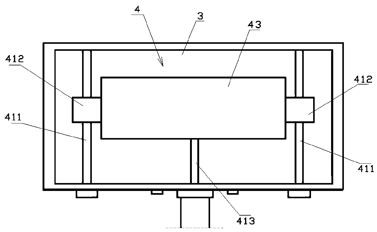
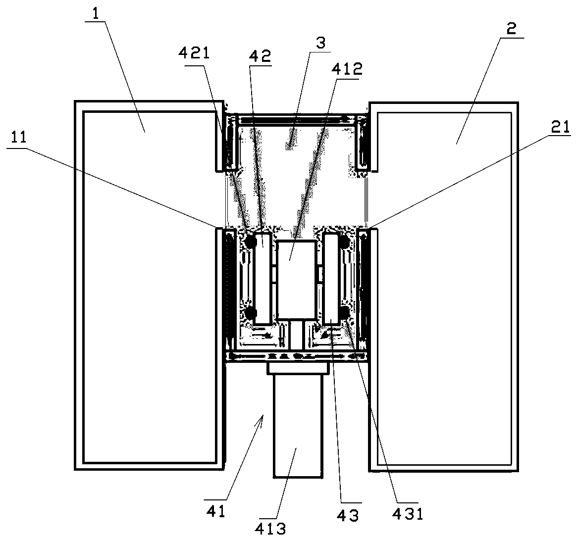
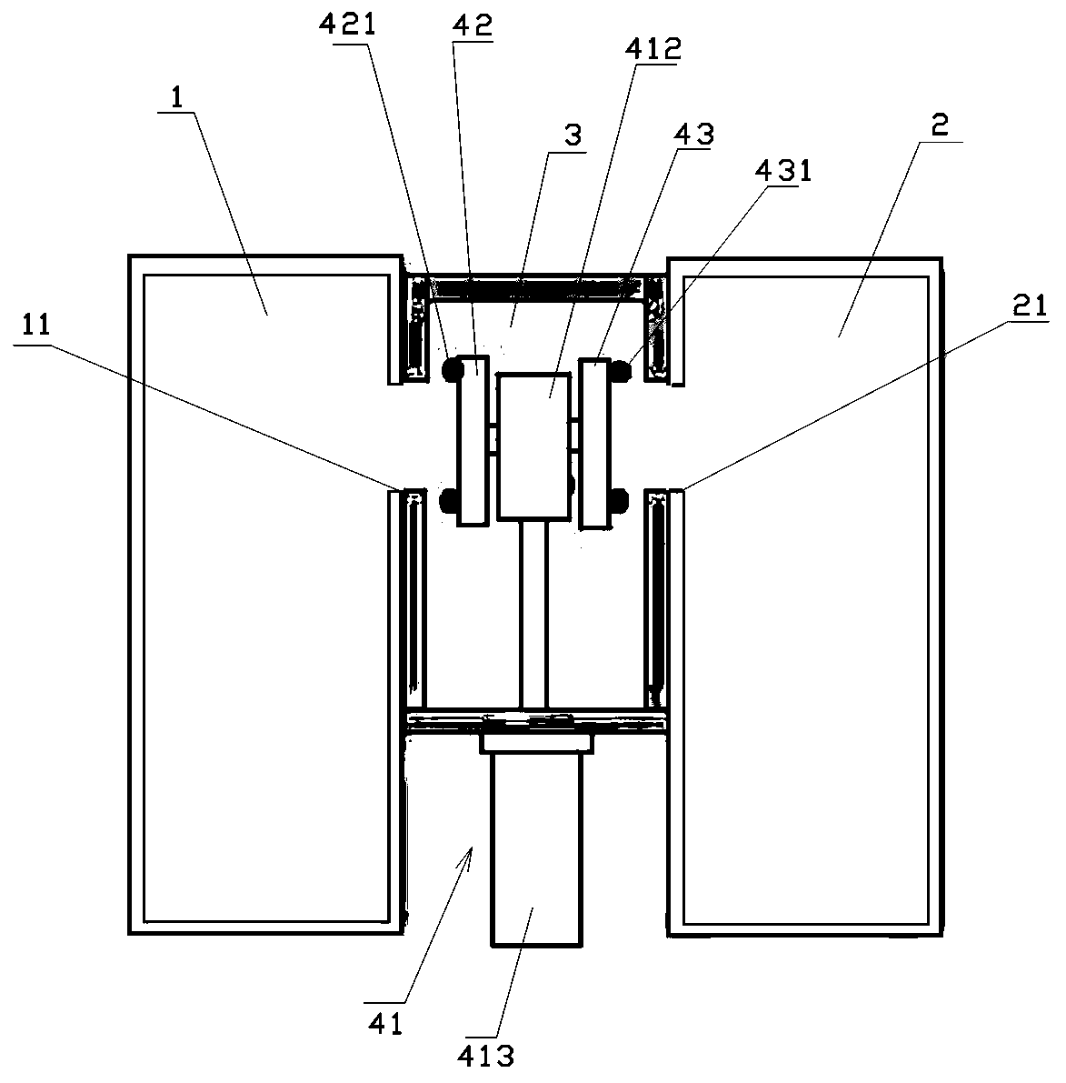
[0025] see Figure 1-Figure 4 , is Embodiment 1 of the vacuum device of the present invention.

[0026] The vacuum device in this embodiment is mainly used in equipment that needs to transport glass substrates in different vacuum chambers, for example: the glass substrate in this embodiment is transferred from the first chamber 1 to the second chamber 2 , and then return from the second chamber 2 to the first chamber 1, during which the vacuum tightness of each ch...


PUM


Abstract

The invention discloses a vacuum device which comprises a first chamber and a second chamber; the first chamber is provided with a first channel port; the second chamber is provided with a second channel port, and a third chamber which is in sealing connection with the first chamber and the second chamber correspondingly; the first channel port and the second channel port communicate with the third chamber correspondingly; a sealing door assembly is arranged in the third chamber; the sealing door assembly comprises a lifting mechanism, a first door body and a second door body; the lifting mechanism can lift in the third chamber; the first door body is arranged on the lifting mechanism and can seal the first channel port; the second door body is arranged on the lifting mechanism and can seal the second channel port; and the first door body is controlled to seal the first channel port and / or the second door body is controlled to seal the second channel port synchronously. With the implementation of the vacuum device, the corresponding chambers can be sealed correspondingly without affecting the vacuum states of the chambers, and the operation effect of the vacuum device can be improved. The vacuum device is simplified in structure and is easy to repair and maintain.

Description

technical field [0001] The invention relates to the field of display panel manufacture, in particular to a vacuum device used in the manufacture of display panels. Background technique [0002] Due to the unreasonable structural design of the vacuum equipment used for driving glass substrates in the prior art, there are mainly the following defects: [0003] 1. The seal is installed on the inner wall of the chamber on both sides of the channel opening. When replacing it, the corresponding chamber needs to be vacuum-broken, which affects the operation effect of the whole machine; at the same time, the operator needs to work inside the chamber , the efficiency is low; [0004] 2. When cleaning and maintaining a chamber with a sealed door, it is necessary to break the vacuum of the corresponding chamber at the same time, and the operator needs to work in a narrow space with a sealed door chamber, which is inefficient. [0005] 3. When the vacuum device is powered off or the C...

Claims


Application Information

Patent Timeline
Patent Type & Authority Patents(China)
IPC IPC(8): C23C14/56
CPCC23C14/56
Inventor 刘永军
Owner SHENZHEN CHINA STAR OPTOELECTRONICS SEMICON DISPLAY TECH CO LTD
Learn More