Eureka AIR delivers breakthrough ideas for toughest innovation challenges, trusted by R&D personnel around the world.

Automatic winding unit for rubber parts

A rubber part, automatic technology, applied in the transportation of filamentous materials, thin material processing, transportation and packaging, etc., can solve the problems of high labor cost, low winding efficiency, easy to cause misjudgment, etc., to improve quality and qualified efficiency, reduce production labor costs, and reduce the effect of waste generation

Pending Publication Date: 2018-06-22
LINK-ASIA SMART TECH (SUZHOU) CO LTD
View PDF0 Cites 5 Cited by
  • Summary
  • Abstract
  • Description
  • Claims
  • Application Information

AI Technical Summary

Problems solved by technology

After winding a rubber part, it is necessary to remove the rubber part and replace another unwound rubber part. During the replacement of rubber parts, the extruder device stops working. After the replacement of the unwound rubber part is completed, it needs to be restarted Start the extruder device, because the rubber at the discharge port of the extruder device is in a high-pressure state when the extruder device is working normally, after the extruder device stops running, the rubber at the discharge port of the extruder device The high pressure state will be gradually released due to shutdown, resulting in a certain length of abnormality in the extruded rubber after restarting the machine. This part of the abnormal rubber will cause a certain length of abnormal rubber strip after entering the molding device. The abnormal rubber strip needs to be manually Manual cutting and manual removal of this part of the abnormal adhesive tape, the work of removing the abnormal adhesive tape is mainly done by workers, so it is necessary to arrange a special operator to complete it, resulting in high labor costs and low execution efficiency, which in turn leads to the overall winding unit The degree of automation is low, and the winding efficiency is not high
And the state of the abnormal rubber strip mainly depends on the operator's experience judgment, which is easy to cause misjudgment and has a certain impact on the quality of the rubber parts after winding

Method used


Image

  • Automatic winding unit for rubber parts
  • Automatic winding unit for rubber parts
  • Automatic winding unit for rubber parts

Examples


Embodiment Construction

[0025] The technical solutions in the embodiments of the present invention will be clearly and completely described below in conjunction with the accompanying drawings in the embodiments of the present invention. Obviously, the described embodiments are only a part of the embodiments of the present invention, rather than all the embodiments. Based on the embodiments of the present invention, all other embodiments obtained by those of ordinary skill in the art without creative work shall fall within the protection scope of the present invention.

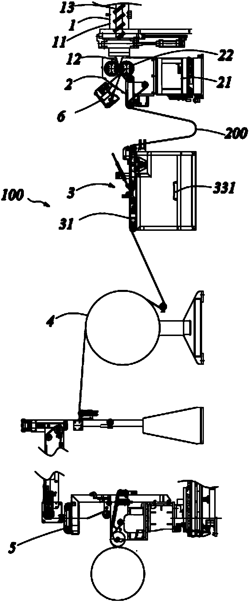
[0026] See Figure 1 to Figure 7 As shown, the present invention provides an automatic winding unit 100 for rubber parts. The winding unit includes an extruder device 1, a molding device 2, an automatic rubber strip processing device 3, a cooling device 4, a winding host 5, and a control device arranged in sequence. system. The extruder device 1 includes an extruder body 11, a material receiving port (not numbered) and a discharge port ...


PUM


Abstract

The invention provides an automatic winding unit for rubber parts. The automatic winding unit comprises an extruding machine device used for extruding rubber, a profiling device used for carrying outrolling forming on the extruded rubber, a winding main machine used for winding profiled rubber strips and a control system; the winding unit further comprises an automatic rubber strip treating device, wherein the treating device is located between the profiling device and the winding main machine, and a cutting device is arranged on the automatic rubber strip treating device; and the automatic rubber strip treating device is used for automatically cutting the profiled abnormal rubber strips through the cutting device, and the cut abnormal rubber strips are automatically removed. The windingunit has the advantages of being high in automation degree, manpower is saved, the winding efficiency is high, and the quality is improved.

Description

Technical field [0001] The invention relates to the field of tire production equipment, in particular to an automatic winding unit for tire rubber components. Background technique [0002] The existing rubber parts winding unit is extruded rubber of a certain shape by an extruder device, and the extruded rubber is molded into a rubber strip with a certain width and thickness through a molding device, and then transported to a cooling device for cooling , And finally transported to the winding host for winding. After winding a rubber part, it is necessary to remove the rubber part and replace another unwound rubber part. During the rubber part replacement process, the extruder device will stop working. After the unwound rubber part is replaced, it needs to be renewed. Start the extruder device, because when the extruder device is working normally, the rubber at the discharge port of the extruder device is under high pressure. After the extruder device stops running, the rubber at...

Claims


Application Information

Patent Timeline
IPC IPC(8): B65H63/06
CPCB65H63/06
Inventor 陈英铸
Owner LINK-ASIA SMART TECH (SUZHOU) CO LTD
Why Eureka
Eureka Blog
Learn More