Winding reel for textile machine
A technology of reel and textile machine, which is applied in the direction of conveying filamentous materials, thin material processing, transportation and packaging, etc. It can solve the problem that the position of reel cannot be adjusted automatically, the installation and disassembly of reel is difficult, and the working efficiency of textile machine is reduced. and other problems, to achieve the effect of fast and convenient disassembly, novel design and convenient use
- Summary
- Abstract
- Description
- Claims
- Application Information
AI Technical Summary
Problems solved by technology
Method used
Image

Examples
Embodiment 1
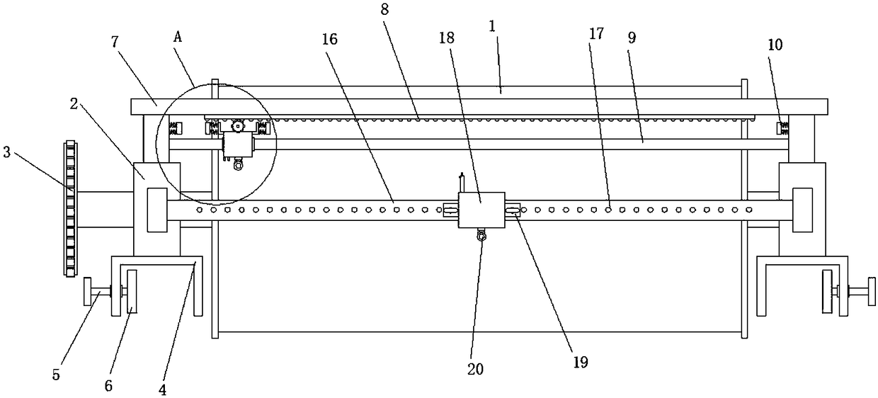
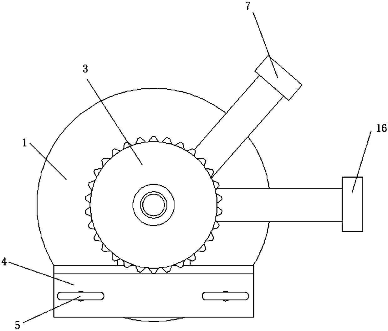
[0024] refer to Figure 1-2 , a spinning reel for a textile machine, comprising a reel main body 1, both ends of the reel main body 1 are provided with limiting plates along the circumference, both ends of the reel main body 1 are connected with support plates 2 through bearings, And one end of the reel main body 1 is connected with a drive gear 3, the reel main body 1 is meshed with the gear of the output shaft of the drive motor on the textile frame through the drive gear 3, and the same side of the two support plates 2 is provided with a U-shaped The clamping block 4, the two ends of the U-shaped clamping block 4 are provided with locking bolts 5 on the same side wall, and one end of the locking bolts 5 located in the U-shaped clamping block 4 is fixedly connected with a compression disc 6, and the main body of the reel 1 is installed on the reel installation frame of the textile machine through the U-shaped block 4, and fixed by the locking bolt 5 and the pressing plate 6,...
Embodiment 2
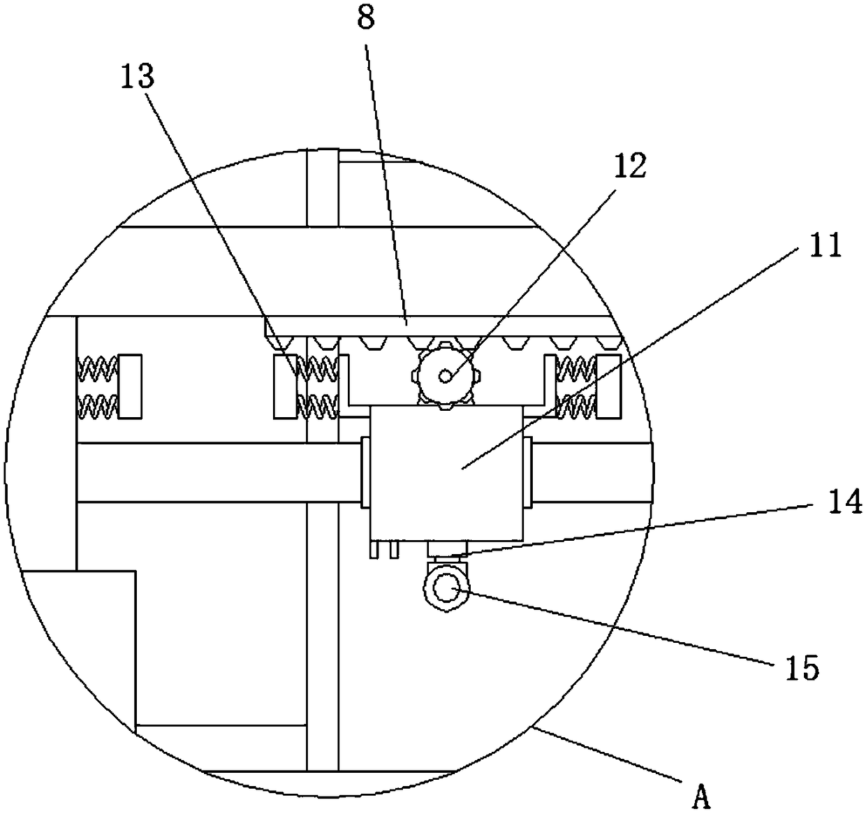
[0027] refer to image 3 , the first wire device includes a first mobile base 11, and the first mobile base 11 is provided with a through socket hole, the first mobile base 11 is movably installed on the first sliding rod 9 through the socket hole, the first mobile base 11 A driving motor 12 is installed near the side of the moving rack 8, and the output shaft of the driving motor 12 is connected with a driving gear, the driving motor 12 meshes with the moving rack 8 through the driving gear, and the first moving base 11 is close to the first touch switch 10 Both sides of the base are equipped with a second touch switch 13 through an L-shaped bracket, and the first touch switch 10 corresponds to the position of the second touch switch 13, and the side of the first mobile base 11 away from the drive motor 12 passes through a universal joint 14 A first wire loop 15 is connected.
[0028] The second touch switch 13 on both sides of the first wire device is in contact with the fi...
Embodiment 3
[0030] refer to figure 1 , 4 , the second wire device includes a second mobile base 18, fixed ears 19 are arranged symmetrically on both sides of the second mobile base 18, and fixed pins are arranged on the fixed ears 19, the fixed pins are connected with the fixed holes 17, and the second mobile base 18 The lower side of the lower side is connected with the second wire loop 20 through the universal joint 14, the second mobile base 18 is provided with a telescopic support arm 21 near the side of the first mobile base 11, and the first mobile base 11 is close to the side of the second mobile base 18 A U-shaped splint 22 is arranged on one side, and the telescopic support arm 21 is inserted into the U-shaped splint 22 in an extended state and fixed by a bolt. The first wire device and the second wire device form a synchronous structure.
[0031]The second wire device can be fixed in the fixing hole 17 on the second sliding rod 16 by the fixing pin on the fixing ear 19, so that...
PUM
 Abstract
Description
Claims
Application Information
 - R&D
- Intellectual Property
- Life Sciences
- Materials
- Tech Scout
- Unparalleled Data Quality
- Higher Quality Content
- 60% Fewer Hallucinations
Browse by: Latest US Patents, China's latest patents, Technical Efficacy Thesaurus, Application Domain, Technology Topic, Popular Technical Reports.
© 2025 PatSnap. All rights reserved.Legal|Privacy policy|Modern Slavery Act Transparency Statement|Sitemap|About US| Contact US: help@patsnap.com