Shot blasting structure

A technology of steel shot and box body is applied in the field of shot blasting device, which can solve the problems of difficult removal and reduce the effect of removing rust, and achieve the effects of preventing pollution, improving the effect of removing rust, and reducing labor intensity.

Active Publication Date: 2018-06-22
江苏明亮减速机部件制造有限公司
View PDF7 Cites 3 Cited by
  • Summary
  • Abstract
  • Description
  • Claims
  • Application Information

AI Technical Summary

Problems solved by technology

[0004] When the shot blasting machine is used to derust the plate, after hitting the plate, the surface of the steel shot is adhered to rust, and the rust is closely attached to the steel shot due to the strong impact between the steel shot and the plate, which is not easy to remove
Therefore, when the steel shot with rust attached to it collides with the plate again, the rust on the steel shot will adhere to the plate again, reducing the effect of removing rust.

Method used


Image

  • Shot blasting structure
  • Shot blasting structure

Examples


Embodiment

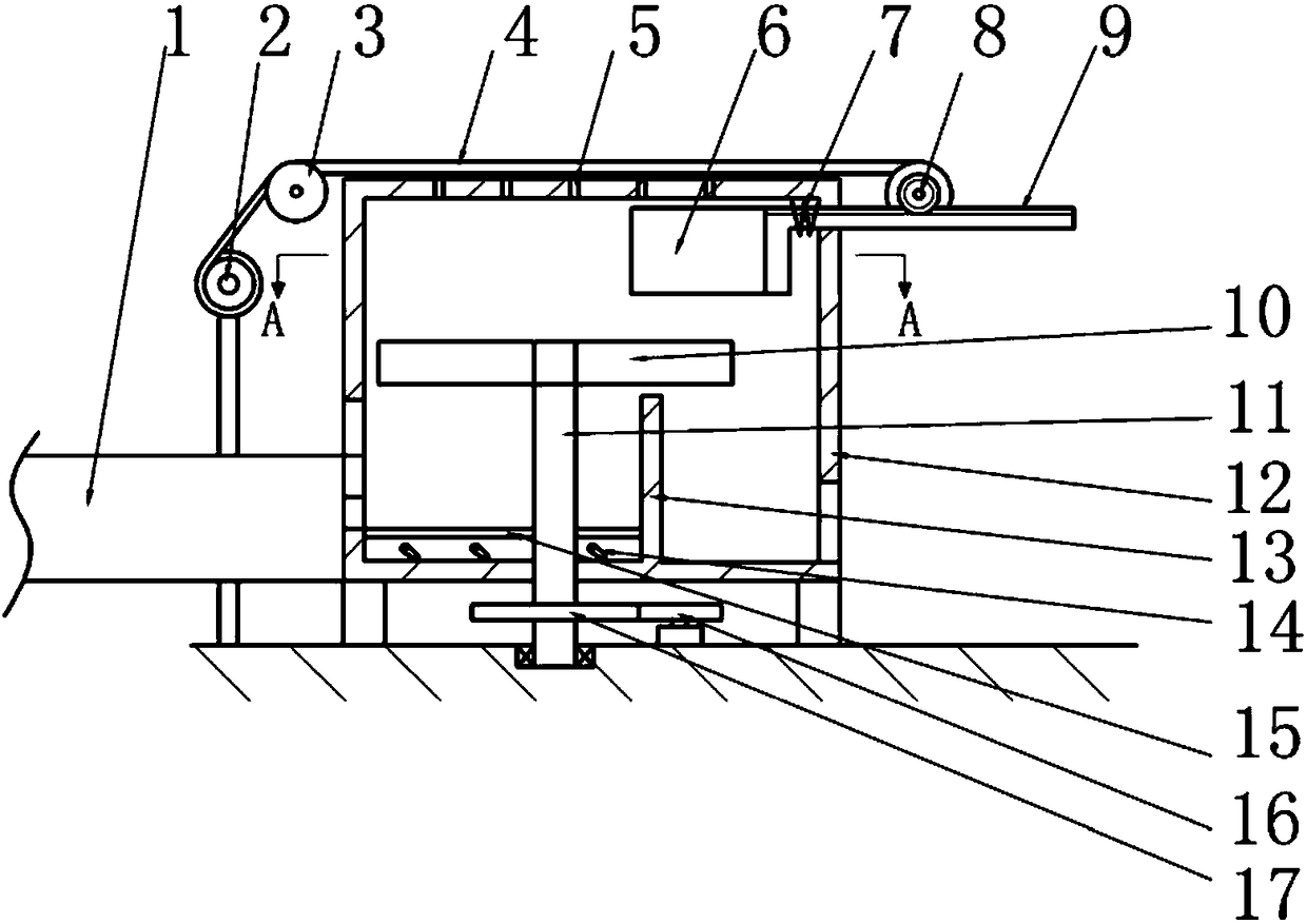
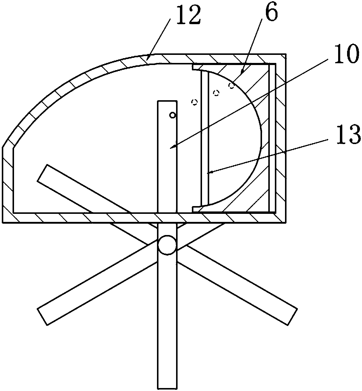
[0020] Embodiment: the shot blasting structure in this scheme, as figure 1 with figure 2 As shown, it includes a screening device, a blade shot separating device and a winding device. The screening device includes a casing 12 and a vibrating mechanism 14. The bottom of the casing 12 is fixedly connected with a box body 12. The clapboard 13. Vibration mechanism 14 comprises vibrating plate 15, and vibrating plate 15 is vertically slidably connected in the screening cavity, and vibrating plate 15 is driven to vibrate up and down by eccentric wheel mechanism, and eccentric wheel mechanism belongs to prior art, does not repeat them here.

[0021] The blade shot-dividing device includes a rotating shaft 11 positioned outside the casing 12 , six blades 10 are fixedly connected to the peripheral side of the rotating shaft 11 , and the blades 10 are positioned above the dividing plate 13 . The blade 10 is inclined along the rotation direction of the rotating shaft 11, so that the s...


PUM


Abstract

The invention belongs to the field of shot blasting devices, and particularly relates to a shot blasting structure. According to the scheme, the shot blasting structure is mainly characterized in thata partition plate which partitions a tank body into a screening cavity and a shot outlet cavity is arranged in the tank body; a vibration mechanism for vibrating steel shots up and down is arranged in the screening cavity; a rotary blade is arranged on the upper portion of the partition plate; the blade is inclined downwards in the rotation direction; the screening cavity is located in the rotation speed of the blade; a sliding plate is slidably connected with the inner wall of the shot outlet cavity; the steel shots can collide with the sliding plate after colliding with the rotary blade; asliding rack is fixedly connected with the sliding plate; a winding gear is engaged with the sliding rack; a winding shaft is connected with the winding gear coaxially, unidirectionally and rotationally; a reset spring is arranged between the sliding plate and the tank body; wet cloth is wound on the winding shaft; a plurality of air outlets are formed in the tank body; the air outlets are locatedover the blade; and the wet cloth is located above the air outlets. The steel shots collide mutually through vibration, and thus rust stains on the surfaces of the steel shots are removed and prevented from contaminating the steel shots again.

Description

technical field [0001] The invention belongs to the field of shot blasting devices. Background technique [0002] Shot blasting refers to throwing the pellets onto the working surface at a high speed and a certain angle by a mechanical method, allowing the pellets to impact the working surface, and then cleaning the pellets and The cleaned-up impurities are recovered separately and the pellets can be reused. Compared with other surface treatment technologies, it is faster and more effective. At the same time, the shot blasting machine is used with a dust collector, and the smoke and dust and attachments generated during the work process are recycled and treated in a unified manner, which is more environmentally friendly. [0003] According to the structure of the casting carrier, the shot blasting machine is divided into drum type, chain plate type, rotary table type, trolley type, squirrel cage type and hanging type shot blasting machine. Drum and chain plate shot blastin...

Claims


Application Information

Patent Timeline
Patent Type & Authority Applications(China)
IPC IPC(8): B24C9/00B24C1/08B07B13/08B07B13/14B08B7/02B08B5/02
CPCB07B13/08B07B13/14B08B5/023B08B7/02B24C1/086B24C9/006
Inventor 苏亚君
Owner 江苏明亮减速机部件制造有限公司
Why Eureka
Try Eureka